|
|
Post by mastertech on Dec 8, 2014 15:56:47 GMT -5
Can you post a picture of the side of that board that has the speaker connectors on it?
|
|
|
|
Post by 24century on Dec 9, 2014 7:45:28 GMT -5
So far it is still not accessible for the speaker terminal board, that lead back to my question 3 days ago when ask help for disassembly.
I am ordering the resistors, will do the test on it when arrived, this way can avoid with full of screws around table and also make the project unnecessary longer, will also post inner parts photos when performing. give me a few more days.
|
|
|
|
Post by mastertech on Dec 9, 2014 9:54:30 GMT -5
You can't take a picture of the bottom of this board (circled in red)? It looks wide open.  |
|
|
|
Post by 24century on Dec 9, 2014 18:47:08 GMT -5
  That I can do |
|
|
|
Post by mastertech on Dec 9, 2014 20:33:18 GMT -5
Just about all those tests points I gave you a few posts back can be done right at the connector pins circled in red. If you want to do the test let me know because if you just want to randomly change stuff I don't want to spend the time posting the info. It takes time for me to work up these tests.  |
|
|
|
Post by 24century on Dec 10, 2014 10:54:53 GMT -5
Sorry to let you feel that I am asking help but doing the own way, I do not like to deal with typo person either.
It is the 1st complicated audio receiver I have ever work on, accessing/disassembly the right part is a bit of challenging without info and experience, otherwise it will not take that long to get the result we are looking for further diagnostic.
Let me get the result as soon and get it post it here
|
|
|
|
Post by 24century on Dec 18, 2014 20:13:10 GMT -5
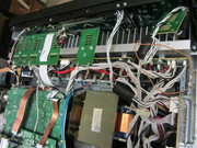
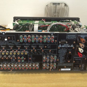
Having a horrible time to disassemble the unit to access the power board (standby board), send Chrisfern (the guy with previous forum who worked on this unit has a successful experience) and ask for advise, hopefully he will response with some useful information, sorry it does takes a lot of longer than I thought it would be
|
|
|
|
Post by mastertech on Dec 18, 2014 21:28:19 GMT -5
No hurry. Take your time.  |
|
|
|
Post by 24century on Dec 30, 2014 18:43:51 GMT -5
mastertech, finally get some quiet time by the end of holiday, I am able to locate the standby board also capacitor C792 however it is not possible to short those 2 legs without opening up the entire board since there are too many ribbons and connectors.
To reach of diagnostic goal of turning on the main transformer, can I go from soldering a directly lie from power in to the main transformer power in connector by totally ignore the standby board?
Since it is a high voltage power related, better ask 1st
|
|
|
|
Post by 24century on Dec 30, 2014 22:01:11 GMT -5
Get the result after putting power directly to the main transformer
BN38
Pin 3-_____4.82
Pin 4-_____0
Pin 5-_____4.75
Pin 6-_____0.02
Pin 7-_____4.81
Pin 8-_____4.82
Pin 9-_____0
|
|
|
|
Post by mastertech on Dec 31, 2014 12:30:55 GMT -5
Get the result after putting power directly to the main transformer BN38 Pin 3-_____4.82 Pin 4-_____0 Pin 5-_____4.75 Pin 6-_____0.02 Pin 7-_____4.81 Pin 8-_____4.82 Pin 9-_____0 These numbers are off the DSP board connector? |
|
|
|
Post by 24century on Jan 3, 2015 13:48:40 GMT -5
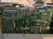
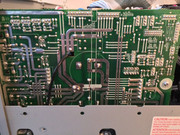
Those #s are measured off from the connector on picture s24.postimg.cc/q8w3ihild/sr7002.jpg that you marked. It appears the main transformer is still on idle even I short the 110v directly, it is still being controlled by the regulation board which is on picture posted It makes no different when bypassing the standby board, Pure Direct/7.1 Input/Clear turns unit on then put power light into 2 sec interval flash. Leaving the standby board power output open does make a difference, 1st power on then 3 keys reset sometime can make the power key works like normal but without the main power, no display, when turning the selector knob (the main turns on the left above the power button), unit may turns on to off. Something is definitely wrong on the regulator board (if I am right, regulator board will be the board picture I posted), need to take that off to do testing. Leaving Monday for CES, looks like this is much more than what I thought and this project is taking much longer, thank you for your patient. Thought I am pretty good among with the people around me but that is wrong too, can't even take a board out properly  |
|
|
|
Post by mastertech on Jan 3, 2015 13:58:46 GMT -5
If I am reading those connector pins right, you need to check the +15v and -15v regulators.
|
|
|
|
Post by 24century on Jan 3, 2015 14:45:24 GMT -5
I am wrong again, it is the power board according to your previous thread with Zerog www.curtpalme.com/forum/viewtopic.php?t=32994Can you point me which connector to measure that +_ 15V, that appear to be the problem or one of the prob, possibly a drawing |
|
|
|
Post by mastertech on Jan 3, 2015 19:44:03 GMT -5
I believe the connector circled in red is the same as the second picture connector. DMM on DC voltage, 2nd pin from top is ground, 1st and 3 rd should test -15v and +15v. Let me know what you get.   |
|