guptau
Junior Member
 
Posts: 90 
|
Post by guptau on Oct 25, 2015 12:05:01 GMT -5
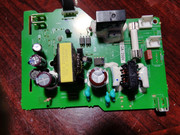
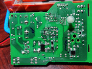
I am hoping that someone can help me fix my tx-nr818 power supply which is not powering the machine. I am a novice in electronics. I was able to disassemble the PS board. I have a DMM and was able to measure the output voltages. According to attached circuit diagram the output should be Ground, 9v, 12v, , , STPOWER and MPOWER (1 to 7 rails). I can get stable 12.35v dc on 3rd rail only. Other rails have very close to zero volts. I have no idea what STPOWER and MPOWER would be but I would expect around 5.6v DC. I am stuck here would appreciate some help. I am attaching the diagram, front and back of the power supply. Thanks. 

 Attachments:
|
|
|
|
Post by mastertech on Oct 25, 2015 20:55:53 GMT -5
There is a good possibility there is nothing wrong with your power supply. The 12v you have is the standby power which is all you would have until the rest of the supply is turned on, via Mpower which should be app 3.3v
But the first thing you must check, after you put everything back together is if it is in protect mode.
Unfortunately, the manual I have does not have any info on resetting.
|
|
guptau
Junior Member
 
Posts: 90 
|
Post by guptau on Oct 26, 2015 8:08:40 GMT -5
Thank you MasterTech! The link to the owner manual is filedepot.onkyousa.com/Files/own_manuals/TX-NR818_English.pdf?CFID=1743667&CFTOKEN=63351772&jsessionid=f0302b7be4e733c70ebc12614b771158514f.
I should have mentioned that the receiver never powered up again once it stopped powering. Not even standby power was on. I tried everything mentioned in the manual as well as suggestions at Onkyo Forum without the receiver powering up again. Since there was no standby power, I suspected the primary power supply to be the problem area and removed it from the receiver. Here is what more I am able ascertain: 1. The filer capacitor is getting 165v . 2. The 3 secondary capacitors get up to 12.35 v. 3. The fuse is good. 4. None of the other capacitors look bad.
Thanks again. Guptau
|
|
|
|
Post by mastertech on Oct 26, 2015 8:59:11 GMT -5
Not sure why you linked me to the OM unless to show the factory reset procedure. This is not the same procedure as to take the unit out of protect mode. Of course we don't even know if it does go dead when a protect circuit is activated. Crap service manual.
What have you done or repaired to bring back standby power? Your 1 thru 4 above is not relevant since you already indicated you have +12vst.
|
|
guptau
Junior Member
 
Posts: 90 
|
Post by guptau on Oct 26, 2015 9:52:37 GMT -5
I have not done anything to do bring back the standby voltage. I have only taken measurements. I when in Protect mode, the standby light should be on. Once the receiver went off, it never came back on including the stand by light. After disconnecting all the speaker I waited 24 hour and pushing the on button does nothing - not even any click sound. I think relevant part from the manual is below. Thanks.
Attachments:
|
|
|
|
Post by mastertech on Oct 26, 2015 11:15:46 GMT -5
I have a little problem believing what that manual indicates in that highlighted section. Most are not like that. But we can continue. But, if we end up tracing this back to the CPU then I will refer back to here.
You clearly have standby voltage because you state you measured +12vst on pin 3 of the power supply. But you do not have the return signal from the CPU to turn on the rest of the power supply. This would indicate 1 of 2 things. Either the turn on signal is not being sent or a short is pulling the signal voltage down to zero. A quick diode test of Q9101 on the PS with the harness disconnected will show if there is a short on that line.
Also, when you tested for that +12vst was the board still in the receiver and everything still connected?
|
|
guptau
Junior Member
 
Posts: 90 
|
Post by guptau on Oct 26, 2015 11:45:47 GMT -5
The power supply is disconnected from the receiver. This is how I have taken all the measurements. You mean Q9101 transistor to be tested without power connected to the board? Or, do you mean out of the board? I will report back at end of the day when I go home from work. Thanks.
|
|
|
|
Post by mastertech on Oct 26, 2015 12:34:05 GMT -5
Q9101 can be tested right on the board with no power.
If it is ok then I would put it all back together so we can do a few tests with power applied.
After assembled I would recheck that +12vst with it plugged in.
Trouble shooting almost always requires the unit to be fully assembled and power applied. Only after some things are determined do you even consider removing boards to test.
|
|
guptau
Junior Member
 
Posts: 90 
|
Post by guptau on Oct 26, 2015 12:55:10 GMT -5
The problem is when fully assembled, the PS board is not reachable for testing. I will try to make the output and the Transformer connections in such a way that the board remains outside enough so that I can take measurements. Thanks.
|
|
|
|
Post by mastertech on Oct 26, 2015 15:48:32 GMT -5
The problem is when fully assembled, the PS board is not reachable for testing. I will try to make the output and the Transformer connections in such a way that the board remains outside enough so that I can take measurements. Thanks. And this will be one of your learning experiences. If you cannot reach a test point when fully assembled then you have to see if the other end of the harness is accessible or you have to put in a fly wire for testing. |
|
|
|
Post by mastertech on Oct 26, 2015 16:52:23 GMT -5
After you get it all back together why don't you try doing a reset that applies to some other Onkyo models.
Press and hold the on/standby and Enter buttons at the same time for 5 to 10 seconds and see if it comes on.
|
|
guptau
Junior Member
 
Posts: 90 
|
Post by guptau on Oct 26, 2015 17:31:35 GMT -5
Hi Mastertech, turns out the Q9101 is a surface mount transistor. No matter what I measure at diode setting, I am getting OL. B -> E OL, E -> B OL, B -> C OL, C -> B OL, and even C -> E OL and E -> C OL. I suspect this could be the cause of the problem.
Tell you the truth, I have tried the resetting option including someothers where you push the power button and one of the input options buttons. It never responded.
Thanks.
Attachments:
|
|
|
|
Post by mastertech on Oct 26, 2015 20:59:45 GMT -5
Well i cannot condemn that transistor just based on your findings. A transistor does not usually go open. This is why tests need to be made in order to confirm if a part is bad or even what direction to be looking at. Shot gunning is a waste of time and not productive.
When you are ready to put it back together and do some tests, let me know. Until then, I'm out.
|
|
guptau
Junior Member
 
Posts: 90 
|
Post by guptau on Oct 31, 2015 14:37:27 GMT -5
Hi Mastertech, I connected everything as before but there is no response from the receiver. I should be able to make some test as the ps is accessible. Please let me know what test you have in mind. Thanks.
|
|
|
|
Post by mastertech on Oct 31, 2015 23:29:54 GMT -5
Ok. Plug in receiver. DMM on DC voltage. Go to that connector on the power supply and use pin 1 for neg probe and pos probe test pins 2,3,6,7.
Give me those readings.
|
|