Deleted
Deleted Member
Posts: 0
|
Post by Deleted on Dec 3, 2015 8:11:00 GMT -5
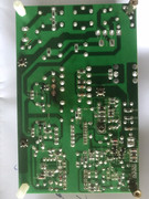
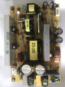
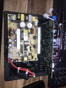
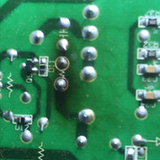
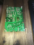
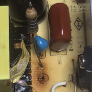
Ok I need some help. I do not have schematics for the Moome and I have a problem that when the Moome is cold it does not boot. Two leds on the back stay on and nothing happens. Normally one goes out (depending on hdmi 1 or 2) and two status leds go on in my case.  IMG_0105 IMG_0105 by Radio Head, on Flickr  IMG_0106 IMG_0106 by Radio Head, on Flickr Now first thing I found was that when i held the board in my hand for some time trying to figure out what was wrong it would suddenly work perfect again. So I thought this might be temperature related and since than I often put the board a minute in the fridge and than it would not boot than I would heat a specifick area and there was an area that responded the best to heating. I circled it in the picture.  IMG_0107 IMG_0107 by Radio Head, on Flickr  IMG_0102 IMG_0102 by Radio Head, on Flickr Now I resoldered everything I could find there (twice I think) but the problem stays. Yes it shows I melted some plastic  After doing the two resistors r337/r336 it was a ok for some time but than came back again when it was really cold. Now it seems to be back again even when less cold. Next thing I want to do is buy some freezing spray. I never worked with it but it might get me closer to the problem place. But what I am trying to figure out now is what chip could cause this led activity and this booting of the Moome. I have no schematics but it seems that the chip that is right behind the leds handles the leds U54. Question what kind of chip could this be? Perhaps when I know how it works I can track better what is wrong. Thanks for thinking along it has been a month now and every time I want to watch a movie I have to preheat the room or the board. Very annoying  I am seriously thinking about buying a new one but than again this one is almost good. Oh it also happens that the Moome just responds very slow. I guess the currents are preheating the board than? |
|
Deleted
Deleted Member
Posts: 0
|
Post by Deleted on Dec 3, 2015 8:27:50 GMT -5
I am thinking perhaps I should ask this to Moome himself?
|
|
Deleted
Deleted Member
Posts: 0
|
Post by Deleted on Dec 3, 2015 10:31:31 GMT -5
Heating on the underside in the same area also works. It also shows the leds connect under U54.  IMG_0108 IMG_0108 by Radio Head, on Flickr I soldered all pins of the U54 chip. I even tried hot air 340 degrees for almost a minute. Does not help. |
|
|
|
Post by Casethecorvetteman on Dec 3, 2015 15:46:42 GMT -5
I am thinking perhaps I should ask this to Moome himself? I think you should send it to him... Before you make it worse. |
|
Deleted
Deleted Member
Posts: 0
|
Post by Deleted on Dec 4, 2015 8:57:12 GMT -5
Yes ok I did that now (send him an email) but it is a puzzle. It should be that area as that chip communicates with the leds. I suspect it is power supply to that chip. Anyway I tested all my Moomes because of this problem. Perhaps interesting I have this very old Moome and I removed the gamma with some jumpers as Moome advices. It has fine bandwidth but the image is very unsharp and noisy. So Moome made a big progress with the later boards  IMG_0109 IMG_0109 by Radio Head, on Flickr I also have a Mike Parker modified Moome. It looks much better in the black levels but is slightly lower in bandwidth accoording to the 1:1 testpictures. I also miss the extreme sharpness that the other Moome gives that is why I try to fix it. Still this one I will try a little bit more. No pictures because of copyrights. Anyway I like the Moome that is sensible to heat most I hope I do not loose it. Perhaps a brand new Moome will be evenbetter? |
|
|
|
Post by mastertech on Dec 4, 2015 11:26:21 GMT -5
You have the right idea and seem to be on the right track. What you also have to remember is the body of a surface mount device can also crack and be intermittent with temperature. I have also had many through hole traces bad and need to be repaired.
If it were me, I would take a bunch of ohm readings (unpowered) of components in that area cold, when it is not working and write them down. Then recheck those numbers after it is hot and working and then compare. If you find any differences it will help to narrow it down.
|
|
Deleted
Deleted Member
Posts: 0
|
Post by Deleted on Dec 4, 2015 11:30:46 GMT -5
Yes thanks good idea. I also had another idea to check. Assuming it might be the grounding I could check all pins on U54 for grounding and solder separate grounding wires. Assuming that the pins are still connected internal what I could also check I guess.
The ohm reading might help to narrow it down if the grounding shot is miss :)Think I could also see if I can find the power pins but grounding seems more obvious because of the large grounding area and the temp response.
|
|
|
|
Post by mastertech on Dec 4, 2015 12:44:29 GMT -5
Do you have access to any components in that area on the board when it is installed?
|
|
Deleted
Deleted Member
Posts: 0
|
Post by Deleted on Dec 4, 2015 12:51:08 GMT -5
Do you have access to any components in that area on the board when it is installed? Normally not but I could solder wires to places. I found the grounding and power pins on U54 and they all seem connected well. I am starting to think it is something else. I measured the resistance of all resistors close and all seem there normal vallue except the ones below R173/R174/R172 There vallues are changing while I measure and are different every time I measure. So I checked C167 but that cap is good. Now I am thinking Q25. It is in the middle of the circle  But perhaps a transistor can have extreem temperature behaviour? I could desolder Q25 and check. |
|
|
|
Post by mastertech on Dec 4, 2015 12:56:01 GMT -5
You are not measuring anything to determine if it is the correct value. In circuit most parts will almost never measure correctly for value. You are just getting a measurement for its "in circuit value", whatever it may be. Then look for any change later.
|
|
Deleted
Deleted Member
Posts: 0
|
Post by Deleted on Dec 4, 2015 12:56:44 GMT -5
|
|
Deleted
Deleted Member
Posts: 0
|
Post by Deleted on Dec 4, 2015 12:58:33 GMT -5
You are not measuring anything to determine if it is the correct value. In circuit most parts will almost never measure correctly for value. You are just getting a measurement for its "in circuit value", whatever it may be. Then look for any change later. Yes I have to wait for the board to get cold again to measure again but the strange thing is the valleus on those resistors are climbing while I measure. |
|
|
|
Post by mastertech on Dec 4, 2015 12:59:06 GMT -5
The reason I asked if you had access when installed is because you could try holding your soldering iron near various components when it is not working to see if it starts working when you have a particular component heated.
You can also throw some pencils with erasers in the freezer and later use the eraser part to cool down specific components to look for reactions.
|
|
|
|
Post by mastertech on Dec 4, 2015 13:00:49 GMT -5
You are not measuring anything to determine if it is the correct value. In circuit most parts will almost never measure correctly for value. You are just getting a measurement for its "in circuit value", whatever it may be. Then look for any change later. Yes I have to wait for the board to get cold again to measure again but the strange thing is the valleus on those resistors are climbing while I measure. Do they react the same if you reverse the leeds? Throw it in the freezer to cool down faster. |
|
|
|
Post by mastertech on Dec 4, 2015 13:04:25 GMT -5
And of course a transistor can have a thermal problem. Any component can.
|
|
 IMG_0105 by Radio Head, on Flickr
 IMG_0106 by Radio Head, on Flickr
 IMG_0107 by Radio Head, on Flickr
 IMG_0102 by Radio Head, on Flickr
 After doing the two resistors r337/r336 it was a ok for some time but than came back again when it was really cold. Now it seems to be back again even when less cold.
 I am seriously thinking about buying a new one but than again this one is almost good.
 IMG_0105 by Radio Head, on Flickr
 IMG_0106 by Radio Head, on Flickr
 IMG_0107 by Radio Head, on Flickr
 IMG_0102 by Radio Head, on Flickr
 After doing the two resistors r337/r336 it was a ok for some time but than came back again when it was really cold. Now it seems to be back again even when less cold.
 I am seriously thinking about buying a new one but than again this one is almost good.


