|
|
Post by gjaky on Jan 31, 2016 12:38:43 GMT -5
I though I create this thread to collect the ideas for performance enhancement in one place, just like with the Marquee thread. Although I know, there is no serious interest in XGs anymore. So far I've found three weak spots in the XGs performance of which two was already discussed on this forum (more or less). In the future I plan to use this thread instead of the previous threads. So for the discovered / known issues: -Later XGs show poor bandwidth, solution is in progress... OLD thread: link-Horizontal retrace is too much for direct use from common HD sources. ->Go to [[old thread]]-Non efficient usage of Focus drive circuitry ->Go to-Fan mod idea ->Go to |
|
|
|
Post by gjaky on Jan 31, 2016 13:11:45 GMT -5
I'd start with the non efficient Focus drive circuitry right away. As known The XGs are fully loaded with the -now hard to find- STK 392-220 type convergence ICs. Focus circuits in NEC projectors always runned redhot, and the XG is no exception, moreover, IMHO they did a step backwards.
All latest generation CRT projectors (EH Marquee, Sony G90, Barco 909) does employ a circuit which regulate the supply voltage for Focus and/or Convergence circuits, making less heat, resulting in more reliable operation.
In 6/9 PG xtra -which as it seems will be an all time favorite- this also was implemented in a way such the focus voltage was proportional to the scan frequency, the lowest supply was limited at +/-15V though.
In the Sony G90 the focus voltage remains +/-15V up to 55kHz line frequency, then it switches to +/-40V operation.
In Marquees not the power supply is adjusted, but resonant capacitors are switched, but the effect is the same: there are three ranges spread through the scan range.
In Barco 909 both convergence and Focus power supply is adjusted proportionally to the scan frequency.
In the XG it seems there is nothing. However there are signs that it was meant to do similar things but it seems it was never implemented -as far as the schematic drawings can tell.
Basically the supply voltage for the Focus drive board is either +/-35V or +/-45V firmly, selected by a jumper on F-Drive board, the schematic diagram indicates the +/-45V as standard, however I'm not sure if this varies by sub type ie. XG75 boards are tied to +/-35V while XG135 boards are set to +/-45V -further investigation is needed.
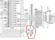
Also there is a control signal going to the LVPS, which is amied to set the focus voltage either high (+/-45V and +/-35V) output or low (+/-35V and +/-25V) output. This signal was meant to set by the system board directly, unfortunately as it seems the contor sub board in the LVPS is not populated. Leaving the Focus supply voltage without control and making the focus board generating enormous heat.
More investigation is needed, for example to find out what actual settings are in my XG135LC.
|
|
|
|
Post by gjaky on Feb 3, 2016 16:36:07 GMT -5
So I investigated the supply voltages. In my XG the F-drive board is indeed tied to +/-48V operation and it did not get any lower at 15kHz.
In the PG xtra, the frequency dependent voltage reaches +/-15V around 40kHz scan frequency, at 97kHz (1600x1200 75Hz) the focus voltage tops at around +/-27V.
I would say this difference in the supply voltage is huge (just as in heat dissipation), but this sure does not that apparent in real life performance.
|
|
|
|
Post by gjaky on Feb 7, 2016 5:38:49 GMT -5
So a little progress have happened. As it seems fortunately the controller in the power supply seems to work. The Focus supply selector voltage is originated on the OSC PWB, from the DY switch signal (deflection yoke switch, turn point at fh=77kHz). On the OSC board it is possible to "select" how this signal is breed: fixed focus Lo V, fixed focus Hi V, select by DY signal. -R5941 is populated by default (at least in my XG1351), this is the fixed high focus voltage mode. -When R5940 is populated with a 100 Ohm resistor that is the fixed low focus voltage mode. -When R5939 is populated with the 100 Ohm that is the automatic mode. Only ONE resitor should be populated at a time. 
I was thinking about an even smarter solution too: -15-30kHz only 25V supply (low focus voltage mode at the 35V focus line) -30-77kHz 35V focus supply (high focus voltage at the 35V focus line) -77kHz-135kHz 48V (high focus voltage at the 48V line) But I really using a single resolution on my XG (1080i-96Hz, fh=56kHz), so I'm fine with the 35V by both method. I have to do tests yet, it even can turn out that the 25V line would be still fine at 54kHz, (with changing to the low focus voltage line), as Marquees are also supplied with 25V focus voltage (and lowered down further with the switched capacitors) too, and the PG xtra only reached 27V focus voltage at 97kHz. |
|
|
|
Post by Casethecorvetteman on Feb 9, 2016 7:27:28 GMT -5
Youre working hard on all this Gábor!! Well done mate  |
|
|
|
Post by gjaky on Feb 9, 2016 12:39:56 GMT -5
What I found lately is that all of the "Drive" boards are supplied from either the +/-48V or the +/-35V line, so with exploiting this voltage switching option all these boards experience lower heat stress, due to the lowered supply lines at low scan frequencies, this sound great, right?
Well, the V drive board too supplied from the +/-48V line, and this is the only board which is not tied to the horizontal frequency (obviously), so in low voltage mode the V-drive only gets +/-35V supply which might turn out not enough in every case, especially if I'd want full V size at 160Hz refresh but with say 33kHz horizontal freq.
But honestly I haven't noticed a single issue with V drive when we watched a full movie with the modified XG (at 1080i-96Hz), here the 16:9 raster usage is sure an advantage.
|
|
|
|
Post by gjaky on Feb 22, 2016 15:26:29 GMT -5
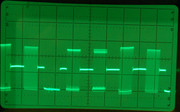
1060P 60Hz multiburst signal on an almost finished XG-VNB neckboard. G1 output, 50Vpp  |
|
|
|
Post by gjaky on Mar 6, 2016 2:24:22 GMT -5
One new thing on the list: H width stability over scan frequency.
I'm not sure if this is a general problem or a failed component causes this but here we go.
The width of the raster on my XG is not stable with scanfrequency. At lower scanrates the raster easily can be set to go off the tube face even without maxing out horizontal amplitude. At 54kHz I daily use I set amplitude at 67% and I can fill my screen. At 81kHz (1080p 72Hz) even the amplitude at 100% and I can't fill my screen -the raster is shrinking. At 2048x1536 75Hz (120kHz) the total projected width is about the half that is at 54kHz scanrate even though when the amplitude was at 100%. This is not a very important feature that's sure, but still bothers me.
The service manual is unfortunately quite vague about this, but it says the +BDEF voltage (supply for the deflection out) is genarated in the PS unit and is controlled by the H-DEF board. The voltage output is 20-200V DC. At 54kHz I measured 100V +BDEF, at 81kHz I only measured 80V, this is odd, although at 81kHz the deflection coils are changed from series to parallel as opposed to 54kHz so in theory at less drive voltage it could deliver more deflection power, I should check if this gets close to 200V at 2048x1536 75Hz that will tell
|
|
|
|
Post by radiohead314 on Mar 6, 2016 6:44:15 GMT -5
Yes I just found out that the 909 smps works with a hthd voltage that depends on line frequency too but it can be manually adjusted For horizontal width. Seems the neck is a bit more complicated in this aspect.
By the way is 50 V not a bit low for the G1?
|
|
|
|
Post by Casethecorvetteman on Mar 6, 2016 7:06:12 GMT -5
Ive never tried 1920x1080 72Hz, but certain resolutions need a lot of amplitude to fill the width. 1280x720 60Hz is one that doesnt fill the width on mine even at 100%
|
|
|
|
Post by gjaky on Mar 6, 2016 13:26:20 GMT -5
I tested at 2048x1536 75Hz (120kHz) with multimeter now and the +BDEF only reaches 105V again, so as it seems there is indeed a problem with the DEF board, the yoke switching has no (or not enough) influence on the +BDEF control voltage as it seems.
|
|
|
|
Post by gjaky on Mar 6, 2016 13:28:15 GMT -5
By the way is 50 V not a bit low for the G1? It can do a bit more, but in push pull this is 100V and that should be just enough, it will turn out anyway. |
|
|
|
Post by Casethecorvetteman on Mar 6, 2016 22:29:10 GMT -5
I tested at 2048x1536 75Hz (120kHz) with multimeter now and the +BDEF only reaches 105V again, so as it seems there is indeed a problem with the DEF board, the yoke switching has no (or not enough) influence on the +BDEF control voltage as it seems. My set is an 852, so it wont go that high. |
|
|
|
Post by gjaky on Mar 12, 2016 16:38:58 GMT -5
I've just bought an XG751 as a spare, and swapped the H-DEF board, and it behaves exactly the same as my original.
|
|
|
|
Post by Casethecorvetteman on Mar 13, 2016 0:56:40 GMT -5
Im not sure which models shared which parts, or if there was any different DEF boards, but it sounds like its working normal to me.
Just set the width pot wider and amplitude menu less.
|
|