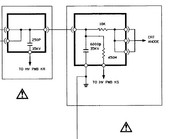
|
|
Post by Casethecorvetteman on Feb 27, 2016 19:16:31 GMT -5
Yes ive seen that one too, seems everyone that has been successful has been in China! |
|
|
|
Post by Casethecorvetteman on Feb 27, 2016 19:18:57 GMT -5
The value of c was about 3nf old style and 6nf new style ,I also think those capacitors are the problem, 2 capacitors in serie without a resistor on them to divide he voltage over them is not good but at those voltages resistors are taking alot of space and to keep heat low value have to enormoes ,and they have to be twice the capacitance to ,any unbalance of voltage will tdamage one. Switching the little boards will require readjustment of the trimmer ,most resistors that can handle high voltages that I have seen are not precise. (5 or 10 percent types) . So what exactly is the purpose of those two caps in series leading from HV to ground? Wouldve thought itd make more sense in parallel... |
|
|
|
Post by gjaky on Feb 28, 2016 1:13:11 GMT -5
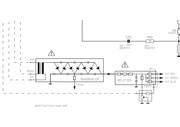
The value of c was about 3nf old style and 6nf new style ,I also think those capacitors are the problem, 2 capacitors in serie without a resistor on them to divide he voltage over them is not good but at those voltages resistors are taking alot of space and to keep heat low value have to enormoes ,and they have to be twice the capacitance to ,any unbalance of voltage will tdamage one. Switching the little boards will require readjustment of the trimmer ,most resistors that can handle high voltages that I have seen are not precise. (5 or 10 percent types) . So what exactly is the purpose of those two caps in series leading from HV to ground? Wouldve thought itd make more sense in parallel... The two capacitors will share the load voltage inversly proportionally to ther capacitance ratio (if their capacitance are the same they share the voltage equally). That said two 20kV capacitor in series can hold up to 40kV, if their capacitance precisely the same. Generally it is advised to connect resistors parallel to these capacitors because the capacitance tolerance are usualy high, thus the dividing factor too. If one capacitor fails then the other will follow it too since it will be more stressed. BTW here is the NEC splitter:  |
|
|
|
Post by Casethecorvetteman on Feb 28, 2016 2:13:52 GMT -5
Thanks for that splitter pic Gábor  Im just a little confused about why they need caps there in the first place??? What would be the likely result of cutting that little black wire and removing them from the circuit? |
|
|
|
Post by Casethecorvetteman on Feb 28, 2016 2:22:17 GMT -5
Then looking at the NEC it seems to have them too, but much higher rated.
|
|
|
|
Post by Casethecorvetteman on Feb 28, 2016 2:26:17 GMT -5
Anyone got the diagram for the Marquee or Ampro splitter?
|
|
|
|
Post by gjaky on Feb 28, 2016 3:23:45 GMT -5
Thanks for that splitter pic Gábor  Im just a little confused about why they need caps there in the first place??? What would be the likely result of cutting that little black wire and removing them from the circuit? The cap help smoothing the HV output voltage, it's no big deal whether if it is before or after the series resistor. Although if it is placed after the series resistor it forms a RC filter but since the series R element is "little" it makes no practical difference in this application. In theory the NEC splitter should work just as well in the Barco, however the 35kV capacitor is not very safe to run at 34.7kV... also the voltage feedback signal have to be done correctly. |
|
|
|
Post by Casethecorvetteman on Feb 28, 2016 10:44:40 GMT -5
Must be something that can be made to work!
|
|
|
|
Post by Casethecorvetteman on Feb 28, 2016 12:09:07 GMT -5
Is there any way we can find out the original specs of the internal splitter components?
I measured 520 ohms between any two outputs, so id have to speculate the resistor value on each output is around 260 ohms.
Between input and any output is around 29.75-29.91k ohms on the 2 R762718 splitters i have here, 6.39nF to ground on one and 6.48nF on the other.
25.4k ohms on the R762210, 3.38nF to ground
|
|
|
|
Post by dummyload on Feb 28, 2016 12:44:19 GMT -5
gjaky ,you have explained it so much better then me,I'm not so good with words an would suck as a teacher.
|
|
|
|
Post by dummyload on Feb 28, 2016 12:52:56 GMT -5
@case , in my ampro4000g the splitter has no extra wires but the hv leads and housing is plastic so no output cap there. Spellman hv is complete hv generator in metal housing. |
|
|
|
Post by Casethecorvetteman on Feb 29, 2016 7:46:07 GMT -5
Yeah thatll be of no use. I havent heard back from the electronics manufacturer i contacted yet, however if we can find certain values for components and how the external trimpot is calibrated itll be very difficult for them to assist.
|
|
|
|
Post by dummyload on Feb 29, 2016 11:42:24 GMT -5
What do you make of the circuit in the splitter where I have put a cirkel around ? Just an idea how to check the trimmer value 1/1000 or how to readjust it ,without the presence danger of hv.(To be clear I still advocate "STAY AWAY OF THIS TRIMMER" just for the people who know what they are doing , I am not responsible for any damage or injuries resulting from this. If we know if the 1/1000 value is with or without the load of the eht board , then we can do something. I will assume it is with ,just a personal feeling so no fact !!!! We need a splitter out of a projector a multimeter or scoop and an adjustable power supply the higher the output voltage the better.(higher feedback output is lower noise) Put the positief lead of the supply to the hv input of the splitter and the negatieve lead at ground on the mini pcb (ground connection of the feedback coax ) power supply at for example 30,00v I will use scoop as example to measurre the feedback output ,input impedance of scoop is 1M so we have to parallel about 640k to get a load of 390,1k (multiple resistors in parallel or a trim) Check with a multimeter if values are correct (390,1k , 30,00v) so now connect scoop to feedback out of the splitter and you should get 30,00mv on scoop.(exactly 1/1000 of input) It's very important that you know you're instruments accuracies. If you use a multimeter witch is normally 10m parrallel resistor should be 406K ,check this with another multimeter. Again assuming that the 1/1000 value is with eht board connected!!!  |
|
|
|
Post by Casethecorvetteman on Mar 1, 2016 1:47:51 GMT -5
Yeah mate i dont know for sure and wouldnt like to speculate on it.
I would say at a guess that the feedback line is calibrated the same on all splitters, and its no problem for a working splitter, but if i was able to get a new one made it may be an issue.
|
|