chad
Junior Member
 
Posts: 21 
|
Post by chad on Mar 17, 2016 10:33:11 GMT -5
Hello. I have a Yamaha receiver RX-V373 that will not power up. When I press the power button, there is no response at all; no relay click. The only time a relay will click is when I press "tone control" + "straight" +"power". There is about 110V coming from the "rails?" of the main transformer. None of the capacitors look damaged, and the fuse tested fine. I am learning about electronics, and am able to solder/desolder. I would really like some help using my multimeter to find the solution to this receiver. Any help would be appreciated!  |
|
|
|
Post by mastertech on Mar 17, 2016 16:40:59 GMT -5
If you hold those 3 buttons for more then 3 seconds does anything on the display light up?
|
|
chad
Junior Member
 
Posts: 21 
|
Post by chad on Mar 17, 2016 17:55:33 GMT -5
I tried hold holding those buttons down for more than 3 seconds; no lights, only the relay click.
|
|
|
|
Post by mastertech on Mar 17, 2016 18:13:36 GMT -5
Well at least it does something. Can you tell if it is the main power relay on the power supply board that is clicking?
|
|
chad
Junior Member
 
Posts: 21 
|
Post by chad on Mar 17, 2016 18:41:43 GMT -5
Yes, the relay on the main power board is the one that clicks.
|
|
|
|
Post by mastertech on Mar 17, 2016 18:46:42 GMT -5
Does it stay latched on or do you hear it unlatch after a few seconds?
|
|
chad
Junior Member
 
Posts: 21 
|
Post by chad on Mar 17, 2016 19:52:19 GMT -5
There is only 1 click from the relay, so I assume that means it's staying latched.
|
|
|
|
Post by mastertech on Mar 17, 2016 20:07:14 GMT -5
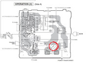
Well lets do some testing and see what we get. Go to the operation 2 board which is the board where the power supply harness goes to. See the attached image. Look for connector CB134. Set your DMM to DC voltage. Plug in receiver and do the button press so you hear the relay click. Put DMM neg probe in the AGND connector and test with the pos probe for the +12v and -12v. Post results.  |
|
chad
Junior Member
 
Posts: 21 
|
Post by chad on Mar 18, 2016 7:24:39 GMT -5
The -12v read .466, and the +12v read 52.6. I noticed the relay does click twice; the 2nd click is about a half second after the first click.
|
|
|
|
Post by mastertech on Mar 18, 2016 11:14:15 GMT -5
Well I guess we can assume the relay is switching back off. So next you will need to solder in a jumper wire on the power supply. On the power supply board locate C1507 and solder a wire across both legs. Now when you plug in the receiver everything will have power even if nothing lights up. So be careful what you touch, even with the probes. Now go back and test for that +12v and -12v.  |
|
chad
Junior Member
 
Posts: 21 
|
Post by chad on Mar 19, 2016 9:09:21 GMT -5
I jumped C1507 legs. The display lit up after trying the power button, and "protected mode" messge came on. I tried holding down the 3 buttons, and the main/"normal" display came up. Now the relay latches for about 3 seconds, then unlatches and the display turns off. I read -12.17v on the -12v, and 12.03 on the +12v.
|
|
|
|
Post by mastertech on Mar 19, 2016 11:58:03 GMT -5
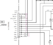
Ok, same board locate CB131 and test the voltages as per the attached image. Use MGND for n_pdet thru +3.3m, use AGND for +5t and +5a, use DGND for +7d and use MGND again for THM1, THM2.  |
|
chad
Junior Member
 
Posts: 21 
|
Post by chad on Mar 19, 2016 14:38:46 GMT -5
Ok, here are the results:
N-pdet 3.28
+3.3m 3.28
THM1 1.520
THM2 1.520
+5t 5.02
+5a 5.04
+7d 9.63
|
|
|
|
Post by mastertech on Mar 19, 2016 16:13:27 GMT -5
This test will be with the receiver unplugged and DMM on diode test.
On the big heatsink there are 2 ic's. IC1 and IC2,STK433-120N-E and STK433-330N-E. Pin 10 on both is ground so put your neg probe on there and then test the other pins with the pos probe and let me know if you get any readings that are low, such as .350 or less.
|
|
chad
Junior Member
 
Posts: 21 
|
Post by chad on Mar 20, 2016 10:12:07 GMT -5
Here are my results with IC1:
1: over .350
2: over .350
3: OL
4: OL
5: OL
6: OL
7: OL
8: OL
9: OL
10: 0.00
11: 0.00
12: OL
13: Ground
14: over .350
15: over .350
16: over .350
17: over .350
18: over .350
19: over .350
Results for IC2:
1: OL
2: OL
3: OL
4: OL
5: OL
6: Ground
7: 0.00
8: 0.00
9: over .350
10: over .350
11: over .350
12: over .350
13: over .350
14: over .350
15: over .350
I put the neg probe in section of a wire harness that a large black wire from the transformer went into (it was easier to leave it there than hold it on a pin from the ic's). If that messes up the results, please let me know and I'll retest with the ic's ground pins.
On the circuit board, the writing said pin 13 was a ground for IC1, and pin 6 was a ground for IC2; but maybe I'm misinterpreting the writing.
|
|