|
|
Post by gregstv on Jan 3, 2017 14:46:52 GMT -5
Using a 100Mhz tektronics 10:1 probe.
I have a 500Mhz 1:1 probe on order. CRO is a 100Mhz. I have done some measurements using the multiburst patten and will post them after work.
|
|
|
|
Post by gjaky on Jan 3, 2017 16:05:10 GMT -5
I guess the 500MHz 1:1 probe is for 50 Ohm termination right? (Do you have a link to it?)
|
|
|
|
Post by gregstv on Jan 4, 2017 6:31:32 GMT -5
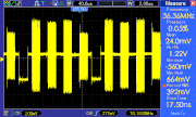
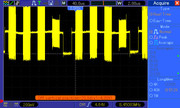
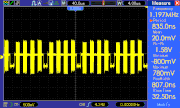
Images using multiburst paten. Input to IFB 11 from MOOME EXT3. Output from IFB 11. Seems to be a bit of added high end. Input to video neck board. This drops off where the IFB 11 has stepped it up. Something in the video processing board between the IFB11 output and the neck board seems to be a bottle neck.    |
|
|
|
Post by gjaky on Jan 4, 2017 14:23:09 GMT -5
The preamplifier boards in the 1292 (CAR, CAG, CAB for each colour respectively) are fully discretely built as far as the video path is concerned each board having several hundred components on it. I always wondered how could they retain the high bandwidth on it, now I know how... LOL  |
|
|
|
Post by gregstv on Jan 5, 2017 2:10:29 GMT -5
There is a 500Mhz (BX6574)amp back before the signal goes to the pre-amp board. This is on the BB board. There seems to be a drop somewhere around this or the switching relays as well.
|
|
|
|
Post by gjaky on Jan 5, 2017 12:36:16 GMT -5
I don't think it is THAT BX6574.
BTW I found MP's 1292 streaking mod thread on AVS, I did not read through the whole, but I catched bits of it, interesting.
|
|
|
|
Post by gregstv on Jan 5, 2017 14:38:46 GMT -5
I will do some checks. The top end is dropping before it gets to the pre-amp board. There is the be amp and RelaCRT Projectorsy for switching between inputs. It could be the coax used as well.
I bet it droppes again on the pre-amp and probably on the neck board.
|
|
|
|
Post by gregstv on Jan 6, 2017 4:15:32 GMT -5
There is a drop through the BX6473. In the part id it says its a switch. Bypassing doesn't work so it must have more to it. Cant find any information for this part. Its on the BB board (signal processing) input and output below. Does anyone have any info on this part?   |
|
|
|
Post by gjaky on Jan 6, 2017 6:20:46 GMT -5
I guess it is a proprietary Sony chip, perhaps the 1292 was the only one where they used it... Well, you have a scope so you can probe what's going in, and what's coming out  |
|
|
|
Post by gjaky on Jan 8, 2017 2:11:17 GMT -5
I've never had a Sony projector actually, but over the years I got some spare boards for them, I have exactly 3 boards for sony 12xx? I never bothered to find out what these boards were as I don't find sony's board naming practice very self explaining. Anyway I took a look what I have, and one of my board is a B board, so I also have a set of those BX6473 hybrids to play with. Maybe I can try to grind off the potting?  |
|
|
|
Post by gregstv on Jan 9, 2017 0:46:27 GMT -5
There is a lot of components in this video chain. I can see the input signal on all inputs to this chip even know I am only using port A. I have bypassed most of the relays and this has picked up the high end quite a bit. Still more to do. I might try running the ibf11 in port b and connecting the pre-amp board directly to it. I can do this by changing the coax connectors around. Just need to remove most of the back part of the projector to get to them. Hope they are long enough to reach the port b connectors.
|
|
|
|
Post by gregstv on Jan 9, 2017 5:24:56 GMT -5
Output of the processor board is much better. looks like there is a drop over the coax to the pre-amp in. The pre-amp board is a part of the neck board assembly. Its like a stacked neck board. after coax on the pre-amp in  before coax. output pin on the processor board  |
|
|
|
Post by gjaky on Jan 9, 2017 6:23:57 GMT -5
Now I would take these measurements with a grain of salt, because all of the on:off patterns go below ground! In this way it is way overpeaked, we don't know if it is really the signal or improper impedances fooling us, this is where the conventional 10:1 passive probes give up.
Consider its 10-14pF tip capacitance forms an input impedance around 100 Ohm (which shunts the 10 MOhm) at 100MHz, plus if you use some crocodile style ground clip, it also adds several nH for ground impedance and there you have a nasty resonant circuit which you attach to the 75 Ohm system.
BTW I could reveal bits of the BX-6473 so far, it looks like it mostly consist of 2SC3839K transistors which in itself isn’t bad at all. A chemist colleague will try to remove the epoxy in a more effective way than using hot air+sharp knife...
|
|
|
|
Post by gregstv on Jan 10, 2017 5:54:46 GMT -5
Don't really care at this stage if the reading is correct or not. I look at the output from the moome as a reference and then look for bottle necks along the very long video chain. Once I get what I can better I will worry about the peaking. With the changes I have made so far the picture is looking much better, cleaner and brighter. I will get some screen shots later in the week.
|
|
|
|
Post by gjaky on Jan 10, 2017 6:30:17 GMT -5
That's OK, but based on the previous scope shots you can't assume much not even for comparison, because I'm 99% sure what you measured there has little connection to the actual signal.
Also I don't question that you could even improve the signal chain without using an oscilloscope. But once you use the scope be aware of the constraints of your equipment so you won't be missleaded.
I went a long way with such measurements myself as well and talk from personal experience, so take it as a friendly advice.
I have here 250MHz-300MHz 10:1 passive probes as well, but they introduce a lot of ringing to the intermediate stages of these video circuits, and when the ringing introduced by the head becomes larger than the actual signal then you can scratch your head, if the scope is actually helping or not.
|
|