nashou
Unmoderated Off Topic
Tech in Training.....
Posts: 1,239 
|
Post by nashou on Mar 18, 2014 16:02:11 GMT -5
but the one in the doc looks like it and has the points in the same spot. And i noticed in the doc they used two different PS pics, the one that is stand alone is like mine the one with all other boards still in chassis is different
|
|
|
|
Post by mastertech on Mar 18, 2014 16:38:29 GMT -5
Right. I think that document was covering 2 different supplies. That is why I said Don't take everything verbatim. Use as guides. Are you good to keep going now? I know you said something about missing the 8v supply. Can you trace on the board? I do not have a schematic for the supply.
|
|
nashou
Unmoderated Off Topic
Tech in Training.....
Posts: 1,239 
|
Post by nashou on Mar 18, 2014 16:41:03 GMT -5
Ok found a board like mine and its cheap so i may take a chance on it. here is the pic  |
|
nashou
Unmoderated Off Topic
Tech in Training.....
Posts: 1,239 
|
Post by nashou on Mar 18, 2014 16:53:10 GMT -5
Right. I think that document was covering 2 different supplies. That is why I said Don't take everything verbatim. Use as guides. Are you good to keep going now? I know you said something about missing the 8v supply. Can you trace on the board? I do not have a schematic for the supply. Yes , I will look at it some more. I'll look for where the 8+ starts and trouble shoot there first. I also may take out the supply and try the out of chassis diagnosis using the jumpers on the alarm board as they call it. I think this allows all voltages to be present where they should be even tho they are not getting the on or off signals from the associated boards. Or at least that is how I think it works right? I think I'll still get that 35 dollar ebay board too. At work right now so this will have to wait till tonight or tomorrow evening. Nashou |
|
nashou
Unmoderated Off Topic
Tech in Training.....
Posts: 1,239 
|
Post by nashou on Mar 18, 2014 17:16:44 GMT -5
 found another pic of the side with the dual buffer outs and the connector where I took the 8.6 v reading. |
|
nashou
Unmoderated Off Topic
Tech in Training.....
Posts: 1,239 
|
Post by nashou on Mar 18, 2014 22:31:39 GMT -5
Ok this is the IC that supplies the 8.6 VDC LM2576 3.0 A, 15 V, Step-Down Switching Regulator pdf.datasheetcatalog.com/datasheet2/d/0j9l2p4l1egh0up8p565iwkoi8cy.pdfI think its ok. I thought pin 3 was shorted to pin 5( the on/off) but the data sheet shows it goes to GND for a fixed output. The other parts that i followed that have a connection from the underside to the 8+ voltage seem ok, there is a cap , inductor , and a diode . My DMM's battery just died but before it did i found a 224 ohm reading between the 8.6 vdc test point next to the connector and GND, and at one end of a resistor. not sure if that end is connected to GND as the battery died. have to look for another DMM for now. |
|
nashou
Unmoderated Off Topic
Tech in Training.....
Posts: 1,239 
|
Post by nashou on Mar 19, 2014 20:45:49 GMT -5
Ok disconnected all connectors and used the jumper for BJ8902 for the OVP/UVP on the small board with the green led. Still no voltage for the 8.6 so I checked the voltage in pin and nothing there either . So more searching. but its hard to follow the traces as its dense with parts and traces get lost. trying to use a flash light on the underside but that too is difficult. Wish I had schematics but no where to be found. board number  nashou |
|
nashou
Unmoderated Off Topic
Tech in Training.....
Posts: 1,239 
|
Post by nashou on Mar 19, 2014 21:58:11 GMT -5
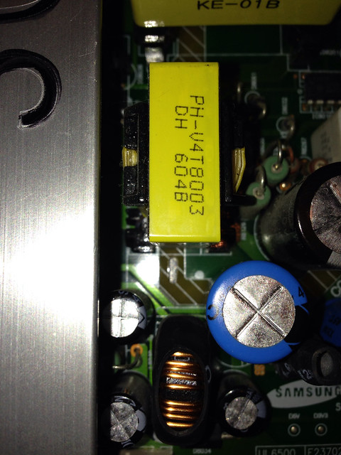
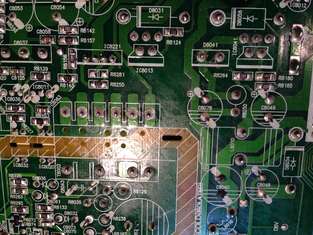
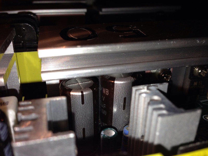
I found two bulged caps under the heat sink overhang i did not notice before. I think one goes to the transformer that should feed the ADJ SMPS regulator of the 8.6 vdc line. Also all pins on that one side show continuity. hard to follow traces as its close to the heat sink. Top of transformer. Low light and flash didn't get down into the board area.   Here is the underside of the PCB, it has the transformer and the SMPS IC8041 the input pin goes to D8041. Hard to be sure if they are ok while in as they measure .1xx or more slowly rising. I guess when I replace the caps I'll remove one leg and check them. I loose the path for the pin 1 past C8078. can't see where it goes on other side either.   One of the bulged caps: the one with the WB on it (C8054 its silk screen is in pic above)  |
|
|
|
Post by mastertech on Mar 20, 2014 9:34:37 GMT -5
Aren't the PS schematics in that SM I sent you?
Edit: I just looked and it appears to be a different supply. Maybe I'll do some hunting later toady. Good job so far though.
|
|
nashou
Unmoderated Off Topic
Tech in Training.....
Posts: 1,239 
|
Post by nashou on Mar 20, 2014 10:25:50 GMT -5
Aren't the PS schematics in that SM I sent you? Edit: I just looked and it appears to be a different supply. Maybe I'll do some hunting later toady. Good job so far though. yeah I think that chassis is different so I didnt even bother looking at it. I bet a samsung 50 inch would be a better chance of having matching boards. The 42 inch PS is identical except for the board number. I wonder if it work incase I cant get this one up and running. Nashou |
|
|
|
Post by mastertech on Mar 20, 2014 11:52:39 GMT -5
CYM
|
|
nashou
Unmoderated Off Topic
Tech in Training.....
Posts: 1,239 
|
Post by nashou on Mar 20, 2014 13:45:40 GMT -5
Thanks for the doc Mac. I'll first check the IC next to those first two caps i replaced at the beginning of this thread. i followed the traces for the 8.6 v line back to the diode next to it and I think it ties to that diode as do those two blown caps. |
|
nashou
Unmoderated Off Topic
Tech in Training.....
Posts: 1,239 
|
Post by nashou on Mar 20, 2014 15:47:36 GMT -5
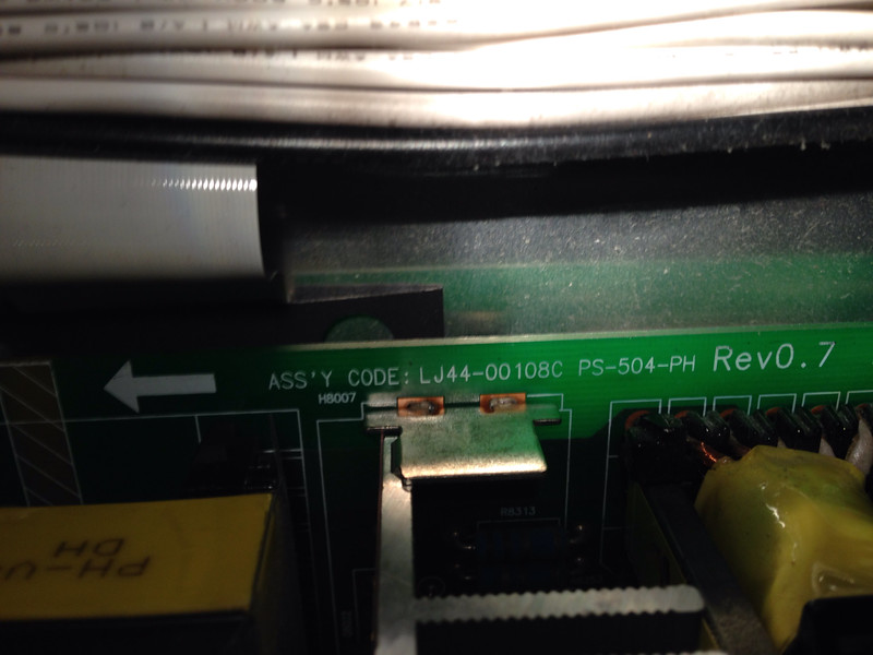
Thanks for the doc Mac. I'll first check the IC next to those first two caps i replaced at the beginning of this thread. i followed the traces for the 8.6 v line back to the diode next to it and I think it ties to that diode as do those two blown caps. Well, really can't tell much for that ic as it measures the same as the other one that is an ADJ type. BUT i did find a fuse blown listed in the error 13 pages of that doc you sent me. It is F8007 a 4 amp 250v. I don't think I'll put it in till I remove those bulging caps, am I right to go that route or should I put it in and power up to see what I get? Nashou |
|
|
|
Post by mastertech on Mar 20, 2014 15:54:34 GMT -5
Yes, replace anything you know is bad before powering it up again. More damage could result if you don't. You really should ESR all those PS caps.
|
|
nashou
Unmoderated Off Topic
Tech in Training.....
Posts: 1,239 
|
Post by nashou on Mar 20, 2014 16:17:49 GMT -5
Yes, replace anything you know is bad before powering it up again. More damage could result if you don't. You really should ESR all those PS caps. Sounds good. Thing is I don't know if my tester works with the caps in the circuit for ESR. i'd hate to remove each one there are A LOT!!! I need to go to RS and get some desolder wick and the fuses. Nashou |
|