|
|
Post by hulio on Nov 22, 2017 5:35:05 GMT -5
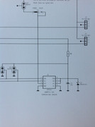
Hello gents, I'm scratching my head about the fan speed-regulator (R763706) in my Cine 9. There are two revisions of them, the newer having some mods done by Barco (addition of a 2V diode near R8 resistor and another value of C5 cap.) When mounted in convergence tray, the older revision gives me "Temperature diagnostics" option in service menu, but no "Voltages diagnostics". With the newer revision mounted, "Voltage diagnostics" option shows back, but no "Temperature diagnostics". Is always one or the other, never both options present. And is not controller dependent (tried with diff. controllers and soft. versions). Projector is working flawless with both and I let the newer revision in (more important to keep an eye on all voltages rather then knowing how hot the projector is), but still..... I would like to get both options. Do you guys with electronics knowledge have a clue ? Mac ? Dummyload ? Greg ?   |
|
|
|
Post by hulio on Nov 22, 2017 5:39:14 GMT -5
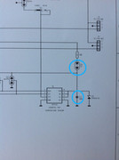
And the schematics   |
|
|
|
Post by dummyload on Nov 22, 2017 11:38:39 GMT -5
The only thing this board does is making a lower voltage from the normal +fan or +12v (depending the jumper on the focus board) for a lower then normal fan speed and it can switch back to the +fan or +12v with the sensor ad7416 switch output.
I would do it the other way to be save for now , I think the board with the extra diode doesn't show temperatuur in the menu because the controller board doesn't see the board so thinking it is not there so front fanes stay always at the lower speed regardles of temperature. )
The only thing the controller does to this board (when it detect it at power up) is putting a temperatuur threshold value in the ad7416
when temperatuur rises above this threshold the switch comes active and connnects the fans back to the +fan or +12v depending the jumper on the focusboard.
I have no idee why they put the diode there but I think the supply voltage for the ad7416 is to low with diode in place .(jumper +fan)
You can do a test and put the jumper on focus board to +12v I bet temperature is now in the menu because the ad7416 has enough supply this way.
Why you don't have both in the menu (voltage and temperature)is still a mystery ,
but I think there is somthing wrong in the I2C bus.
|
|
|
|
Post by hulio on Nov 22, 2017 18:35:35 GMT -5
Thanks for the input, Dummyload.
I'll play tomorrow with the jumper on focusboard to see the outcome. No I2C bus errors detected. Besides, I have tested both boards in another Cine 9, with the same behaviour.
|
|
|
|
Post by mastertech on Nov 22, 2017 18:41:10 GMT -5
I dont think the 2v means 2 volt. I think it means the style of the diode, note the 2 diode symbols. Are there any numbers on the diode? Can you do a dc voltage test on the output of the diode? Also. I think you dont have the temp in the menu because there is something wrong with that board. Do you know if the projectors will read both temp and voltage at the same time with fully functioning boards?
Is S1 set the same on both boards?
|
|
|
|
Post by dummyload on Nov 23, 2017 5:50:52 GMT -5
@ mastertech Measuring the voltage on pin 8 of the ad7416 is indeed a better way to find out if the board with the special diode is faulty. With fully functioning boards the voltage and temperature is shown in the menu. When I visited Hulio more then a year ago ,I brought a working controller and fan board and the voltage was also abcent in the menu so the problem is not in the tray and this is why I think there is a problem on the I2C bus ,problem is we don't know how the program is written regarding problems on the I2C bus.(does the program only check the acknowledge bits for errors?) If I remember correct the controller only looks at start up if the fan board is present (through the I2C bus) if not the temperature line is not present in the menu. S1 wil make no difference regarding controller and menu. hulioI would replace al boards on the chasis that are using the I2c bus and use the fan board without the diode in the tray and see if that makes a difference in the menu.(I think you have a spare of al boards?) |
|
|
|
Post by barclay66 on Nov 23, 2017 5:53:39 GMT -5
Hi,
First some general information on Barcos and their usage of I2C devices:
Barco projectors determine the presence and version of most boards by scanning the I2C bus for acknowledge signals. E.g. the presence of a Convergence-on-Green will be evident in the menus only if the I2C bus scan returns an acknowledge signal from the I2C address expected for a COG board (there seems to be a table of known I2C addresses in the firmware).
Many boards have more than one I2C device on them (especially the many electronic potentiometers) and there's a large variation of I2C device types.
For sensors there are three main variations: A sensor which itself is an I2C device (like the AD7416 on the fan speed regulator), an I2C A/D converter which translates voltages into digital values or an I2C I/O device which returns status (on/off) signals.
I2C errors will be issued if:
- The I2C bus is stuck (either data or clock line permanently high or low)
- Required acknowledge signals are missing (e.g. defective or missing non-optional boards)
- Timing issues are present
- Unexpected I2C acknowledge signals are present (this isn't verified yet)
In case of the fan speed regulator, the AD7416 will listen to address 4Bh. The firmware should show the temperature information as soon as the sensor is visible on the I2C bus. I don't know what Barco intended with the modification on the board. The capacitor doesn't do any harm but the diode could reduce the supply power for the sensor. You should measure the supply on both boards (pin 4 -> GND, pin 8 -> VDD at the AD7416). According to the datasheet, the supply voltage needs to be between 2.7V and 5.5V for correct operation.
I don't know where the sensing and I2C conversion are being done for the voltage display. It could be that the menu only supports one line for displaying either temperature or voltage. In this case, with temperature sensor being present, it could override the voltage display and would show the temperature instead.
Regards,
barclay66
|
|
|
|
Post by hulio on Nov 23, 2017 6:48:37 GMT -5
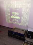
Thanks for your time guys. Some update. Putting the S1 jumper from the focusboard on +12V position didn't changed a thing (still voltages diagnostics option only, no temp. diag.) I measure 1,88V DC on the diode output, and is not broken (OL reading when change polarity). Position of S1 jumper is the same on both boards (front). Yes, both temp. and voltages option should be present in the service menu. Here a screenshot of Redfox's projector showing that. If I remember correctly, it was with CineMax V2.13 software. Could be the only soft. version that recognise both options ?  |
|
|
|
Post by hulio on Nov 23, 2017 7:14:14 GMT -5
I will replace all boards indeed, to rule out a hidden I2C bus error.
|
|
|
|
Post by dummyload on Nov 23, 2017 7:23:29 GMT -5
Well 1,88v is to low ,(as barclay66 wrote) seems like the diode is dead because on the board (photo) it hangs directly to the input voltage so 1,88v is not possible with working diode but best to check voltage on input diode to be 100% sure.So the this board with the diode doesn't work (stays always in slow fan mode) so boards in the tray can overheat without an error or warning.
Hulio in this case it is not about software version ,because remeber my controller and fan board did the same in your projector=no voltage diagnotics in menu (have both in my projector)
so your controller or fan board without the diode is working fine it is elsewhere .
|
|
|
|
Post by mastertech on Nov 23, 2017 9:57:18 GMT -5
I would also like to see what the voltage is on the other side of that diode. The feed voltage.
|
|
|
|
Post by hulio on Nov 25, 2017 19:02:24 GMT -5
Alright, with exception of the EHT, quad and splitter, all boards were swapped. I even used another chassis, to rule out the mainboard too. Unfortunately, with the same result.
So I put the second fan-board with the diode mounted (from the backside of the projector) into the conv. tray, changed the S1 jumper to "front position" and took some voltage readings. On the AD7416 chip, the following reading were measured:
Pin 1=1V
Pin 2=4,2V
Pin 3=4,4V
Pin 4=0V
Pin 5=0V
Pin 6=4,8V
Pin 7=4,8V
Pin 8=4,8V
Input diode D4=7,3V
Output diode D4= 5,5V
|
|
|
|
Post by mastertech on Nov 25, 2017 19:57:07 GMT -5
Pin 1 is a problem. Remove harness from J5 and retest voltage at pins 1 and 2.
|
|
|
|
Post by hulio on Nov 26, 2017 7:46:52 GMT -5
Removing connection with the controller (J5), gives me a reading of 0,24V on both pins (1 and 2).
|
|
|
|
Post by mastertech on Nov 26, 2017 11:28:01 GMT -5
I am assuming you means pins 1 and 2 of ad7416? Also test for dc voltage at the harness that you removed from J5. 2 pins should have around 5v and the last is gnd.
|
|