|
|
Post by barclay66 on Jan 25, 2018 6:49:14 GMT -5
Hi,
I have received the unit for repair. First of all, I did an assessment of its current status.
Appearance:
- Mechanically and optically pristine
- Completely clean (air filter looks like new)
Things that work:
- All of the operating controls on the device itself and on the remote
- Power sequence
- Lamp (404hrs on it, 408hrs total)
- Fans
- Optical block (SXRD panels, iris, lens, alignment etc.)
- All of the internal menus
- Analog Input (VGA-Connector), perfect picture at 1280x768/60 (maximum res), EDID (DDC) data can be read from this port
Things that don't work:
- Either of the two HDMI inputs, not being recognized as display device when connected to a PC, no EDID data visible
Looking at the service manual leads me to the area around IC202 (HDMI input selector and buffer).
The next step will be measuring all relevant power rails (SUB5V, SUB3.3V, D3.3V) and if those are on spec then measure the activity of the HDMI data lines at the inputs and output of IC202.
According to its data sheet (TMDS261B) and how it has been implemented in the Sony, IC202 is controlled via several logic inputs. It would make sense, checking their status while switching the inputs via the remote. This could lead to the decision, if replacing IC202 could be the right way to go or if the problem could be related to the main signal chip (IC205). If this should be the case, I'd rather try to get a new QA board as I neither have the equipment nor the experience for replacing such a BGA chip.
What do You guys think?
Regards,
barclay66
|
|
|
|
Post by gjaky on Jan 25, 2018 14:40:10 GMT -5
I've heard different HDMI switchers going bad in TVs, it also make sense since they are directly connected to the "outside" word and they get every crap people thowing at it.
|
|
|
|
Post by mastertech on Jan 25, 2018 16:19:09 GMT -5
I have come across many of blown HDMI chips both in and out. Not uncommon. This does not appear to be a BGA ic. Are you sure it is or did you mean just ic205?
I would like to see the supply voltages first also. If they were good then I would test for shorted control lines for both HDMI inputs. They can be short to each other or shorted to gnd or pwr. None of the input control lines should show short to anything.
Did you test the RGB input also? I believe you indicated you did with the VGA test but just want to be sure. It is somewhat tied to the same control of the HDMI in's.
|
|
|
|
Post by barclay66 on Jan 28, 2018 7:25:39 GMT -5
I have come across many of blown HDMI chips both in and out. Not uncommon. This does not appear to be a BGA ic. Are you sure it is or did you mean just ic205? Did you test the RGB input also? I believe you indicated you did with the VGA test but just want to be sure. It is somewhat tied to the same control of the HDMI in's. Hi, the HDMI chip is in a TQFP-64 package. Although it's a challenge, I might be able to swap it. IC205 is the video processor in a BGA package. The analog input works flawlessly (VGA input tested only, I don't have a component source). Regards, barclay66 |
|
|
|
Post by barclay66 on Jan 28, 2018 7:40:04 GMT -5
Hi,
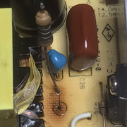
I opened up the unit and removed the QA board. By visual inspection it became obvious that HDMI input #1 has received a major punch. Several parts are burnt or even have disintegrated and at least one trace is burnt (see PCB picture). With measurements I was able to identify all defective or supposedly defective parts (see schematic excerpt) and have already ordered replacements (total value less than $30). Although it isn't certain that I will be able to revive HDMI input #1, I'm confident that HDMI input #2 might work again after swapping the switcher chip. At least I was able to dump the contents of its EDID EEPROM (24C02) which will be needed for programming the replacement on input #1...
Regards, barclay66


|
|
|
|
Post by mastertech on Jan 28, 2018 11:09:56 GMT -5
the HDMI chip is in a TQFP-64 package. Although it's a challenge, I might be able to swap it. Regards, barclay66 Have you ever used " Chip Quik"? If you want I can write up a "how to" from my experience on replacing these multi pin ic's.. |
|
|
|
Post by barclay66 on Jan 28, 2018 12:05:52 GMT -5
Hi,
Thanks, that would be excellent. I‘ll use any help I can get...
Regards
barclay66
|
|
|
|
Post by mastertech on Jan 28, 2018 19:49:59 GMT -5
Ok. You did not say if you have used Chip Quik or not so I will start there. This stuff works great and works just like in this video. Nothing magic about the process. I have it on hand at all times and have used it many, many times. So here is a video. I will continue in next post. Digikey sells it and probably many other places too.
|
|
|
|
Post by mastertech on Jan 28, 2018 20:13:22 GMT -5
After the ic has been removed and the board is all cleaned I begin to prep the board for installing the new ic. I put some flux across all the ic pads on the board and then I take my solder and apply a small amount on each pad. Not a lot of solder, just enough to cover the pad area. And not very deep either. Just enough to cover the pad. I continue until all pads are individually covered. I use a 60/40, 60% rosin core, 1.2mm diameter solder. Just indicating what I use but I am sure something else would work. But I like the narrow solder for this work since it is easier to control the amount of solder on the small pad. And I use a narrow pointed tip on my iron.
Next, examine each pad to be sure none of them are bridged.
Once satisfied all pins are coated and no bridging you take the new ic and place it onto the pads taking your time to be sure each pin is directly over its pad. Take your iron and go to a corner pin, holding the ic with 1 hand and iron in other and put iron on 1 pin and press down very lightly until pin sinks into solder and quickly remove iron. Iron should be hot enough so the pin sinks within seconds of iron placement. If still satisfied with ic position, go to opposite corner and do the same with that corner pin. If still satisfied do the remaining 2 corners. If position still good then pick a side to start with and then just go down the side, 1 pin at a time, just long enough to sink the pin and move to the next. I usually count the pins as I go along so the number I solder equals the number of pins per side minus the corner. Then continue around the remaining sides.
This sounds like a long process but for this number of pins ic it would only take me around 120 seconds to completely solder in place. I am sure you will want to take your time on the first one but they get easier. I have done up to 200 pins ic's with ease. Maybe even higher pin count. I do not remember for sure.
As you will see you do not want a lot of solder on your pads. If there is to much, your iron will start to pick up solder. You would then need to wipe your iron every once in a while so it does not drip on your board or ic or bridge any pins. You can look over your work with a magnifier after done to check for any bridging. Most of the ics I have done you can not even tell they were replaced. I comes out that neatly.
Let me know if you have any questions.
|
|
|
|
Post by barclay66 on Jan 29, 2018 7:28:26 GMT -5
Hi,
Thanks! I should be able to give it a try now. I will let You know how it worked as soon as I receive the parts ordered and after finding the time for working on it...
Kind Regards
barclay66
|
|
|
|
Post by barclay66 on Feb 5, 2018 4:28:06 GMT -5
Hi,
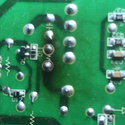
It works! Well, at least HDMI Port #2 (which is sufficient to me). HDMI Port #1 will now return EDID data to the source but there's no picture. Later I found out why: I didn't check the resistor packs at the switcher's inputs! Those are clearly dead too and I overlooked that. I might finish the repair some time in the future and only if I have to open up the unit anyway: The QA board is buried under the optical block and disassembly takes some time. In the pictures You can see the switcher chip after replacement, the PCB area with defective parts removed and the same area after replacement. I had to add one wire jumper due to the disintegrated trace and for one transistor and the double diode I didn't get the original parts but replacements with a different case...
  
Kind Regards, barclay66 |
|
|
|
Post by gjaky on Feb 5, 2018 6:13:08 GMT -5
Barclay, It looks great! So did you end up with Chip Quik, or how did you remove the TQFP chip? So is that going up next to the Marquee?  |
|
|
|
Post by barclay66 on Feb 5, 2018 7:09:06 GMT -5
Hi,
I went for a rather "brute force" approach as the chip was dead anyway: I took a very fine needle which I could use for going under the pins, applied a solder blob on each side, added some additional flux and went heating each side while lifting the pins with the needle. All pads were left unharmed. After that, I cleaned the area with solder wick, positioned the new chip and soldered the outward pins to their pads. On each side, I then applied flux and fresh solder creating solder blobs again. After removing them using solder wick and after cleaning, the result is like in the pictures. Before doing all this, I practiced on an obsolete hard disk controller board.
The marquee is still being used on a daily basis. Before working on mods and testing, I still have some other projects ahead:
- Arduino-based RS232 control for selectively controlling all of the AV gear. I want to be able to selectively switching on/off all devices in the correct order for a signal chain ending up either at the Marquee or at the Sony. So, each of them will require adequate output settings on the Lumagen (e.g. 1080p24 for the Sony or 1080p72 for the Marquee when watching Blu Ray) and an individual power up and power down sequence (e.g. leaving enough cooling time for the Sony). I will control the Marquee, the Sony, the Denon amplifier and the Lumagen via RS232 and will apply power to them via relays. The only unit being constantly powered will be the remote box itself.
- Modifying my son's active speakers (the ones I built last year) for balanced inputs and digital crossovers (Yamaha D1030/DDL3)
- Building my own active speakers (Toslink inputs, DSP-based active crossovers, ICEpower digital amplifiers, remote control)
- One or two smaller repairs on audio gear
Kind Regards,
barclay66
P.S.: You're a moderator now? When did this happen?
|
|
|
|
Post by gjaky on Feb 5, 2018 7:46:44 GMT -5
Looks like you are not going to get bored in the upcoming year  Yeah, it looks like I became a moderator just yesterday LOL. This happened mainly because the Admin asked me for it, and in fact I was quite hesitant to do so, but here we are...  |
|
|
|
Post by barclay66 on Feb 19, 2018 4:31:40 GMT -5
Hi,
Finally, I got around replacing the resistor packs at HDMI input #1. Good thing is that I could do that without having to remove the board. I only had to remove an air duct which was covering it:
This shows the defective resistor packs. Please note the four small craters on each of them: 
This is the area after removing them and cleaning: 
These are the new ones in place: 
Now the unit is fully functional again!
Kind Regards, barclay66
|
|


