|
|
Post by tjmotter on Dec 11, 2018 9:40:07 GMT -5
Ok, I'm an idiot and missed two transistors, Q4903 and Q4904. Forgot to soldered them back in. After I have soldered them in, the two resistors R4905/R4906, smoked out again. I have also measured pin #91 and 92 using pin #90 as ground. The resistance, at both pins shows 1.4Mohm. That means, that Q4001 is not shorted? After replacing the two resistors, I have assembled everything and using two meters at +7V/GND/-7V (ran wires to the top), the voltages are not going right to +/-7V, it starts building up, from around +2.4V/-2.4V, but I have unplugged it quickly at this stage. I have to confess, that I have found a solder blob between, two joints and I assumed, that blob must of caused the smoke, but it seems like, it wasn't the case. Should I cut the traces, that lead to pin #91/92, of the Q4001, to exclude that IC? When I measure the pair of transistors, at this 12V to 7V power supply, they all show weirdly, like they conduct each way. They show 0.5V, 1.2V. But out of the circuit, they measure as they are good. Q4142 does not appear to be damaged. There is no short, between pins #4 and #8. I need help here. Could anybody help? I would appreciate it a lot. I wouldn't cut any traces. If you absolutely want to isolate this power going to this chip I would start by removing R4901, R4902, R4905 and R4905. These parts are MUCH easier to remove than Q4001 and removing them will disconnect the +7/-7 volt rails from the +12/-12 volt regulators. Note that the -7 volt signal also connects to C4052 so that needs to be checked.
At this point all signs are pointing to Q4001 being blown. This is consistent with the damage I have observed on other Onkyo's that were hit by a lightning surge. As I have said in the past, removing this chip is an absolute last resort. Onkyo glues this chip down at 4 points and this board is single sided which means they don't etch a board, they glue a plastic overlay that has the traces built into it. The end result of this is that when you try to use heat to remove the chip, the overlay bubbles up making it VERY difficult to mount a replacement.
|
|
|
|
Post by tibimakai on Dec 15, 2018 14:44:24 GMT -5
What I'm trying to do, is to separate the +/-7V supply from Q4001, to see, if they deliver the right voltages. When I daid that would cut traces, is between the Q4001 and +/-7V supply. There are some wider traces, that could be cut. I wouldn't mess, with those thin ones, though.
If the resistance between pin #91/92 to pin #90 is 1.4Mohm, how come Q4001 is shorted? Where would be that short? What I'm trying to find out, how would I know, if Q4001 is shorted, or not?
|
|
|
|
Post by tjmotter on Dec 16, 2018 8:25:39 GMT -5
Removing those resistors will accomplish the same thing. Since they supply the voltages (+/- 7V) to the device, removing them is the same as cutting the traces. This device is essentially an Op Amp on steroids. You can't test for ground because an op amp doesn't use ground the same way as other devices. Here is a link that will describe what you are up against: www.edn.com/design/test-and-measurement/4389306/The-basics-of-testing-op-amps-part-1--br--Circuits-test-key-op-amp-parametersI suspect that you have a problem on the input side of the op amps. The only way to check this is to measure the resistance of the +/- inputs on each channel (for example, pin 5 and pin 6) to see if one of them has a low impedance. A typical op amp will have a high impedance on the inputs but a low impedance on the outputs so you have to do this for every set (pin 2/pin 3, pin 7/pin 8 etc.). Note that according to the block diagram, +/- 7V is also driving Q4201 and Q4301 but I don't see how they are connected in the schematic. You may want to check them as well (same procedure as Q4001). |
|
|
|
Post by tibimakai on Dec 17, 2018 11:22:15 GMT -5
You have lost me, about these op amps. We are talking about the NJM4580 ICs, right?
|
|
|
|
Post by tjmotter on Dec 17, 2018 14:47:09 GMT -5
You have lost me, about these op amps. We are talking about the NJM4580 ICs, right? NJM4580's are op amps but so is NJW1298 (Q4001). Q4001 simply has some extra circuitry to allow it to also act as a switch.
My previous note showed the incorrect pin numbers. One of the steps in testing an opamp is to check the input impedance. On Q4001 this means each of the following pairs needs to be measured:
Left Channel: Pin 47/Pin 70 Right Channel: Pin 50/Pin 69 Center Channel: Pin 68/Pin 78 Surround Left: Pin 77/Pin 67 Surround Right: Pin 76/Pin 64 Surround Back Left: Pin 75/Pin 63 Surround Back Right: Pin 74/Pin 62
All of these measurements should be very similar (and should be fairly high values).
|
|
|
|
Post by tibimakai on Dec 27, 2018 1:04:07 GMT -5
I had a bit of time and I have checked C4052, which is OK, out of circuitry, in it, shows 77uf(47uf).
I have also measured, those pins and they all show the same thing, they start around 123 Kohm and the numbers start increasing.
Next, I will have to check Q4201 and Q4301.
Which pins I would have to check on these?
|
|
|
|
Post by tjmotter on Jan 10, 2019 11:42:42 GMT -5
I have no idea how to test these two devices but I would start by measuring the resistance between pins 21 and 22. Next, I would measure both of these pins to ground (pin 20) to see if there are any obvious shorts. Next, I would remove the resistors that feed the power into them and then turning on the unit to see if the +7/-7V rails on are working properly on Q4001. The four resistors you would need to remove are: R4231, R4232, R4331, R4332. Each of these is a 220ohm 1/4watt resistor (you may also want to measure each of these to see if any are shorted. Removing these resistors will isolate these chips from the power rails and if they are the issue, the rest of the system should start up. Note, there are also 4 "Mute" transistors in this circuit (Q4241, Q4242, Q4341, Q4342) that serve the same purpose as the mute transistors that were blown earlier in this thread. I would check each of them to see if they are shorted.
|
|
|
|
Post by tibimakai on Jan 13, 2019 20:52:13 GMT -5
I have did those measurements, and I did not see anything wrong.
By the way, the Q4301 and all the peripheral components, are not populated(maybe on the 900 model).
I'm measuring the +/-7V output resistance, and there is a 2 Mohm resistance on each side.
The 4580 ICs don't have short between pins #3/4/8 either.
+/-12V supply is not shorted either.
I have soldered three wires to the +/-7V output, to be able to monitor the output, when the receiver is assembled and two of them, were very close to each other.
I'm wondering, maybe they have touched each other, after assembly?
I will throw it together, and I will try it out again.
|
|
|
|
Post by tibimakai on Jan 14, 2019 18:22:38 GMT -5
I'm thinking of trying out, powering only this board, from a +/-12V power supply and see what is going on, without assembling the whole receiver.
What do you think?
|
|
|
|
Post by tjmotter on Jan 15, 2019 8:35:03 GMT -5
That approach might help narrow down the issue but be aware that you will be bipassing all of the protection circuits so it could also cause additional damage.
|
|
|
|
Post by tibimakai on Jan 15, 2019 10:54:36 GMT -5
Good point. I hate that, I'm not able to see what is going on down there.
|
|
|
|
Post by tibimakai on Jan 19, 2019 18:48:02 GMT -5
I have managed to put it together and placed two meters at the +/-7V output and this is what I get. It does not look good, specially at the -7V side.  |
|
|
|
Post by tjmotter on Jan 20, 2019 10:57:12 GMT -5
I hate to say it but it seems like it is time to remove that part (Q4001). I don't know of any easy way to do this without damaging the board. If I had to try to remove one of these again my current thinking is that I would probably lay a thick bead of solder across all of the pins to stabilize them and then try to cut the top of the pins free from the chip. Once I had the pins free, I would then desolder them all and try to pry that chip off of its glue spots. HUGE risks with this approach since you could cut a trace while trying to cut the pins or while trying to pry the chip off. Even worse, you could tear the PCB. I am not even sure how I would cut the pins. One thought is a dremel with a cutoff wheel but if it slips at all, it will definitely destroy the board..... As I stated before, I have replaced these types of chips in the past but in 100% of the cases, the PCB bubbles up making it very difficult to solder the new chip down. Even worse, I don't know where you will find one. A dealer at Alibaba offers one on their website but it is impossible to say if they really have stock.
Have you checked all of the other opamps to see if they could be dragging the -12V (and thus, the -7V) line down? Q4101, Q4121, Q4141 and Q4142 all use the same voltage rails.
|
|
|
|
Post by tibimakai on Jan 20, 2019 13:56:31 GMT -5
The resistance varies at the ops amps, hard to say it they are good, or OK. I think, that the easiest is to remove them all and try again the measurement.
I will have to pick up another receiver, like 545 or 646 and harvest the IC from that. I think there is one on Ebay, that is local and they ask $40 or make an offer.
I would also like to be sure, that the +/-12V to +/-7V source is working well, before I would do all this work. When I measure the transistors, I can't be sure if they are OK or not. They show in to many ways in circuitry.
|
|
|
|
Post by tibimakai on Jan 20, 2019 18:25:51 GMT -5
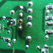
I ended up cutting the two traces(+7V and -7V) and the voltages went up to +/-6.94V. To me, this way it seemed like the easier route. I will clean the green stuff up and resolder the two traces.
I went with the dremel at it. Forgot that you have mentioned, to solder all pins together, my bad. Will cost me some tedious repair. Luckily I have a scope now.
Managed to rip a few traces, when I was removing the legs with the solder iron, or when I used the dremel.
Only thing left is, to pry up the IC. Could I use some kind of Acetone, or something that would melt the glue?
|
|


