|
|
Post by tjmotter on Sept 15, 2019 7:29:04 GMT -5
The voltage test will require the unit to be plugged in and turned on so be careful.
The Mute circuitry testing requires that the system be turned off and unplugged. There are two sections that you will need to check. The first is on the HDMI board and will require you to check Q7002, Q7003, Q7004, Q7005, Q7006, Q7007, Q7021 and Q7023. Each of these transistors should give the same readings when you test them with your meter. If any are different, replace them.
The second set of transistors is on the bottom of the main amp board. You may be able to test all of these by identifying the "AMUT" signal and checking to see if it is tied to ground. If so, one of those transistors is bad but they are all in parallel so it will require you to remove them one by one until you find the bad one (or bad ones).
|
|
|
|
Post by trytofix on Sept 15, 2019 17:09:07 GMT -5
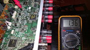
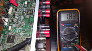
The voltage test will require the unit to be plugged in and turned on so be careful. The Mute circuitry testing requires that the system be turned off and unplugged. There are two sections that you will need to check. The first is on the HDMI board and will require you to check Q7002, Q7003, Q7004, Q7005, Q7006, Q7007, Q7021 and Q7023. Each of these transistors should give the same readings when you test them with your meter. If any are different, replace them. The second set of transistors is on the bottom of the main amp board. You may be able to test all of these by identifying the "AMUT" signal and checking to see if it is tied to ground. If so, one of those transistors is bad but they are all in parallel so it will require you to remove them one by one until you find the bad one (or bad ones). Ok Todd, did the testing though I don't know if I did it right thats why I am uploading pictures hopefully they help, see readings below: below ones read 1.36v:        these ones read 3.35v:     these ones fluctuate between 1.84 and 1.83:        the 5v ones read 5.19v:     I tested all 3 voltage regulators and they also read deferent they were a nightmare for the red lead and my eyes:    I will check the mute transistors on the HDMI 1st and see what they read.. and how do I identify the "AMUT" signal can you elaborate more please.. as for the DSP before I turn one the heat gun is there a way to know if all the solders are attached or we just assume and reflow them? thank you Todd for your amazing help.. |
|
|
|
Post by tjmotter on Sept 15, 2019 17:34:35 GMT -5
If you look through the schematic and search for "AMUT" you will find that it is a signal that is passed from the HDMI board down to the Amp board so you should be able to probe it with your meter without removing the HDMI board.
Unfortunately there is no way to know if all of the solderballs are connected. All you can do is reflow the chip and hope for the best.
HTH
Todd
|
|
|
|
Post by tibimakai on Sept 16, 2019 10:21:27 GMT -5
Since that plastic connector is melted, to me it looks like, somebody already tried reflowing the DSP. It did not work out, and he sold it.
|
|
|
|
Post by tjmotter on Sept 16, 2019 10:26:58 GMT -5
The voltages look "close enough". I don't see the picture with the melted connectors but ALWAYS mask the area off with Kapton tape and then again with a layer of tin foil to contain the heat. At 435 degrees EVERYTHING will melt including plastic parts, labels and the solder on all devices near the DSP. If you mask it off correctly you won't break anything and the components will stay where they are supposed to.
|
|
|
|
Post by trytofix on Sept 16, 2019 16:24:53 GMT -5
|
|
|
|
Post by tjmotter on Sept 17, 2019 9:53:05 GMT -5
I am going to need a little time to work through these pictures. In the mean time, if you are using the Service Manual for the NR626 from Electrotanya, I would recommend that you download the version for the NR828. The reason is that the NR626 version they have is a scanned version so you can't search on it. The NR828 is the same PCB but it allows you to search for a specific component.
HTH
Todd
|
|
2tone
New Member

Posts: 3
|
Post by 2tone on Sept 17, 2019 14:20:16 GMT -5
Hi hope its ok to post in this threid, I've an onkyo tx-nr515 thats not getting an ip would I be right in think that this is the same process that i will need to go through "reflow the bga chip" behind the eathernet port.
|
|
|
|
Post by tjmotter on Sept 17, 2019 15:41:40 GMT -5
You should first try to reset the Receiver (press and hold CBL/SAT then while holding it, press "ON/STANDBY"). If that doesn't work my next question would be: Does everything else work? If yes, you likely have a broken solder ball and a reflow would be a good idea. If no, it could still be a broken solder ball but if you have no sound, the chip could have failed.
|
|
|
|
Post by tjmotter on Sept 17, 2019 16:15:18 GMT -5
On the schematics, "AMUT" is repeated multiple times on the HDMI board and I don't know how to probe it. I was testing the mute transistors and they don't all read the same, I was only able to locate four of them on the HDMI board I don't know if the rest are supposed to be under the board. As for the plastic connector, it is not really melted, its kind of bent from the heat as you can see in the pictures below. you also mentioned the voltages being "close enough" so is it still ok? I am going to reflow the DSp but I don't have the flux that you suggested at the beginning of this thread, but I am working on getting it. I am uploading pictures, maybe you could spot something I might have missed, particularly on the DSP. I think this is more on the output relay or terminal board I just don't know what to test or check  The 470uF 6.3V capacitor in this picture stabilizes the power to the HDMI portion of the MUTE circuitry (those transistors I mentioned). You should check the voltage across this to see if it is delivering a stable 5V.
On the bottom of this picture are 3 connectors. The one on the left most side is P8001B. The AMUT signal passes through this connector on pin 21. This equates to the 2nd pin of the connector as I show in the attached picture. To understand if this circuit may be the issue try the following and report back your results:
1) With the board out of the system, measure this pin to ground. It should show a high resistance. If it is shorted to ground, this circuit has a problem.
2) If it shows high resistance, install the board in the unit. Set your meter to "volts". Touch the black lead to a ground point (top of an HDMI port) and touch your red lead to this pin. Monitor the voltage after turning the receiver on. It should jump up to 5V. If it doesn't, the issue is likely with one or more of the mute transistors on the HDMI board but if it does, you will have to check the mute transistors on the bottom of the amp board.
 |
|
|
|
Post by trytofix on Sept 18, 2019 16:12:11 GMT -5
On the schematics, "AMUT" is repeated multiple times on the HDMI board and I don't know how to probe it. I was testing the mute transistors and they don't all read the same, I was only able to locate four of them on the HDMI board I don't know if the rest are supposed to be under the board. As for the plastic connector, it is not really melted, its kind of bent from the heat as you can see in the pictures below. you also mentioned the voltages being "close enough" so is it still ok? I am going to reflow the DSp but I don't have the flux that you suggested at the beginning of this thread, but I am working on getting it. I am uploading pictures, maybe you could spot something I might have missed, particularly on the DSP. I think this is more on the output relay or terminal board I just don't know what to test or check  The 470uF 6.3V capacitor in this picture stabilizes the power to the HDMI portion of the MUTE circuitry (those transistors I mentioned). You should check the voltage across this to see if it is delivering a stable 5V.
On the bottom of this picture are 3 connectors. The one on the left most side is P8001B. The AMUT signal passes through this connector on pin 21. This equates to the 2nd pin of the connector as I show in the attached picture. To understand if this circuit may be the issue try the following and report back your results:
1) With the board out of the system, measure this pin to ground. It should show a high resistance. If it is shorted to ground, this circuit has a problem.
2) If it shows high resistance, install the board in the unit. Set your meter to "volts". Touch the black lead to a ground point (top of an HDMI port) and touch your red lead to this pin. Monitor the voltage after turning the receiver on. It should jump up to 5V. If it doesn't, the issue is likely with one or more of the mute transistors on the HDMI board but if it does, you will have to check the mute transistors on the bottom of the amp board.
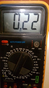
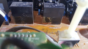
 Ok, I read your post while I had the HDMI board out to check the speaker relays, I noticed one of them shows certain yellow residue or some sort you will see it on the picture below. I am not sure if that is right. I am not sure what you meant by the 470uF 6.3V capacitor on the picture the capacitor near the connector is not 6.3v its 16v!!? As for the resistance on the connector, while the board is completely out of the system, I checked the resistance of the pin on the connector you mentioned P8001B, and it is just flat, the meter read nothing but after putting it back to the system without connecting all the other connectors, while the meter is on 2M the resistance was showing .224,.225 and when the meter on 20M shows 0.22 this must be high resistance. I connected all the other connectors, the result was the same on the resistance, as for the voltage I turned on the device on FM, USB and NET the meter was set on 20v DC the voltage is 2.66v when I changed the front input buttons from FM to TV/CD, PC or GAME etc. the voltage shows -15.00v I dont know what that means but I haven't seen 5v even running the device for a about 30min I even checked on the side board where the pin correspond where it is written AMUT it is giving me the same result. I was thinking of running the system while the HDMI board is out of the system I dont know if that is correct. this is just to test in general if the HDMI is the main collaborate on no sound out using the fm input?!.. please let me know what you think of the speaker relays specially the front L/R channel on the picture below. Measurements:        Speaker relay:       |
|
|
|
Post by tjmotter on Sept 18, 2019 16:54:01 GMT -5
C7006 is the capacitor I was referring to. It stands alone just to the left of the DSP. This should be a 470uF 6.3V.
Not sure I am seeing what you are seeing on those relay's. It looks like someone wrapped the base of them in Kapton tape.
There isn't much you can do with the HDMI board out of the system. The Main CPU is located on the HDMI board and without it, the system won't turn on.
I am not sure where the -15V is coming from. I am not aware of anything on the HDMI board that would push a -15V signal....
|
|
|
|
Post by trytofix on Sept 18, 2019 17:32:58 GMT -5
C7006 is the capacitor I was referring to. It stands alone just to the left of the DSP. This should be a 470uF 6.3V. Not sure I am seeing what you are seeing on those relay's. It looks like someone wrapped the base of them in Kapton tape. There isn't much you can do with the HDMI board out of the system. The Main CPU is located on the HDMI board and without it, the system won't turn on. I am not sure where the -15V is coming from. I am not aware of anything on the HDMI board that would push a -15V signal.... I see, so I measure the capacitor the same way I measured the connector pin, while system running black lead on ground and red lead on one side of the capacitor?.. if so, then when on Tuner, USB etc. I get 3.98v and when BD/DVD, PC etc. I get 4.04v.. this means the capacitor is no good I guess!!? I think it gave me -15v maybe, if not unusual because I set the multimeter to 20v!!.. I will try a different multimeter.. The relay yah its the Kapton tape, but wandering why that specific relay had this yellow kind of oily looking!!.. but maybe that one is more exposed to heat!.. |
|
|
|
Post by tjmotter on Sept 18, 2019 20:34:34 GMT -5
3.98V or 4.04V isn't different enough to cause a problem. I will try to fire up a system tomorrow and check what the AMUT line should read.
|
|
|
|
Post by tjmotter on Sept 19, 2019 12:46:49 GMT -5
Ok, I learned something new today. When an Onkyo Main CPU wishes to mute all channels, you will see ~2.5V on the AMUT signal. When it wishes to unmute all channels, the voltage on the AMUT signal will jump to -15V. From this it would appear that your HDMI board is working properly so the issue could be either the MUTE signals on the Amplifier board or the Speaker relay circuit.
Can you perform the following test for me?
1) Connect everything up but use headphones instead of wiring up the speakers
2) Turn the system on
3) Select "TUNER" and press the dial buttons until you get a good signal
4) monitor the AMUT signal with your multimeter and wait until it shows -15V
3) Let me know if you have any sound from the headphones
|
|