|
|
Post by beagle39 on Sept 5, 2019 3:13:15 GMT -5
Hi all first post so apologies if i've missed an intro thread my issue is this:
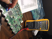
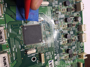
i have 616 which was displaying the hdmi fault, so i removed the pcb attempted to reflow chip rechecked no change i then attempted a second time this time heating for a longer period after this a new problem came up when the amp was plugged in the 9v relay on the power supply pcb just clicked constantly and not power up.
So i thought i may have caused a short on the board and the unit was going into a protect state, i checked the pcb over could not see anything obvious i then removed dts chip completely and reballed, before resoldering i connected the pcb back up to the amp same fault (9v relay clicking). Im now at a point were i have refitted the chip and the power fault is still present.
I have also just had the ribbon cable from the psu connected with no other connection to the pcb and the fault was still present.
Any help would be gratefully appreciated
|
|
|
|
Post by tibimakai on Sept 5, 2019 10:41:54 GMT -5
I'm in the same boat with an older unit. On mine the HDMI iC was overheating. Before I have touched it, it was working, except the HDMi part.
After I have replaced two times the HDMI IC(different IC), all I'm getting, is this relay constantly clicking.
I was suggested to replace the relay, the resistor before it and a transistor. I haven't had time to do this job yet.
|
|
|
|
Post by tjmotter on Sept 5, 2019 15:33:09 GMT -5
|
|
|
|
Post by beagle39 on Sept 6, 2019 8:05:03 GMT -5
Thanks for info although i'm not sure my problem is the relay as i'm seeing power on transformer when i short out pins 1 and 3 on P901B connector (this stops the relay clicking)
|
|
|
|
Post by tjmotter on Sept 6, 2019 12:52:43 GMT -5
P901B is the power input on an NR616. You should check that diode. This is a common problem on your generation. I doubt that it is related to your repair, it just happens.
|
|
|
|
Post by beagle39 on Sept 9, 2019 3:48:33 GMT -5
Sorry my bad i meant JL901A connector the relay engages when pins 1 and 3 are shorted, i have removed power pcb and will test it separately, so if i was to input a 12vdc between pins 1 and 3 of the JL901A connector the relay should stay on, would this be enough to confirm the problem is elsewhere ?
|
|
|
|
Post by tjmotter on Sept 9, 2019 6:27:25 GMT -5
That relay is a 9V so simply place a 9V battery across its leads to test it. You will still have to check that diode though. The way this circuit works is that when the Main CPU sends the signal to turn on that relay, Pin 126 goes high. This drives a couple of things but in this circuit, it applies power to the base of a prebiased NPN transistor which turns it on allowing current to flow from the collector through the emitter to ground. On the other side is a 12V supply line connected to a 150 ohm resistor which (now that it has a source to ground) brings the voltage down to 9V. This in turn allows current to flow through the relay turning it on. BUT, Onkyo installs a small diode in the reverse direction to protect the Main CPU (and in theory that transistor though it often blows when hit with reverse current). My current theory is that when that resistor drops below 146 ohms, it increases the voltage/current just enough to blow this diode (and often the transistor) causing the symptoms you are seeing. Essentially, the MAIN CPU is trying to turn on but is sensing a reverse flow of electricity coming from the transistor and immediately shuts down to protect itself. You can bridge anything you like but understand that if you force this circuit on and it blows that MAIN CPU, you are screwed. That CPU has internal flash and can only be replaced if you have the correct flash programmer (and of course, the code for an NR616). Oh yeah, Renessas (who makes this CPU) won't sell it to you. I have tried ordering it through Mouser and Digikey and the answer is a flat out "NO".
When you bridge pins 1 and 3 on JL901 you are essentially bi-passing the transistor and applying ground directly to the relay/diode allowing the flow of electricity through the relay. This doesn't tell you if the diode is bad but it is a strong indicator (to me) that the transistor is blown. These are pre-biased transistors so there is no easy way to test them. Fortunately they are cheap so replacing it is the easiest option. As I said before, if the resistor has degraded it usually damages the coil in the relay, the diode as well as the transistor so if you don't change them all, expect it to happen again.
HTH Todd |
|
|
|
Post by beagle39 on Sept 9, 2019 8:00:53 GMT -5
ok thanks i will check diode, i have the power supply completely separate from main unit and testing as a standalone unit as to not cause damage to anything else
|
|
|
|
Post by tjmotter on Sept 9, 2019 9:34:38 GMT -5
Measure the resistance across the coil of the relay as well. The datasheet says it should be about 324 ohms +- 10%. If it has drifted too far off of this consider it damaged and plan to replace it. If you try to measure it while on the board note that the diode (and a capacitor) sit across those two contacts so you may have to test it in both directions.
|
|
|
|
Post by beagle39 on Sept 17, 2019 15:27:53 GMT -5
Just an update checked psu all seems fine and also swapped out from another unit to comfirm.
|
|
|
|
Post by tjmotter on Sept 18, 2019 15:38:36 GMT -5
If it isn't the power circuit, it is most likely a component that has failed into a short on the HDMI board. Time to do some deeper diags on the board. I would suspect that the SII part is the most likely culprit so to check this, can you take a measurement of the resistance at TP8303 to ground as shown in the attached picture? TP8303 is the 1.2V rail. In my experience, the resistance of this line to ground is a good indicator of the health of the HDMI chip.
I took this from a working board and as you can see it shows close to 500 ohms. I would consider this to be a perfect board. I have another that reads 335 ohms. This one works but the chip is showing signs of wear. Anything under 200 ohms I would consider garbage.
  |
|
|
|
Post by beagle39 on Sept 18, 2019 16:09:52 GMT -5
Ok will only have time for this quick check tonight but i'm reading 300 ohms
|
|
|
|
Post by tjmotter on Sept 18, 2019 20:37:00 GMT -5
300ohms is high enough that it shouldn't be causing the continuous restart but it is low. A brand new part should read over 700ohms. It is possible that it is failing into a short as soon as power is applied. I would install the board in the system, place a probe on that test point and turn on the system to see if you are getting 1.2V.
|
|
|
|
Post by tibimakai on Sept 19, 2019 10:16:59 GMT -5
It is so good to see you helping these people on this forum. You are awesome Todd. I'm working on a TX-NR555 now.
|
|
|
|
Post by beagle39 on Sept 19, 2019 15:09:47 GMT -5
Measured test point powered its fluctuating between 0 and 0.5vdc as the relay opens and closes , if the 3 way cable is not connected to JL801B i'm reading 1.3vdc @ the test point and no clicking relay, not sure this information helps but found by accident by forgetting to connect
|
|