|
|
Post by serafis on Oct 15, 2019 3:41:30 GMT -5
Hi, I'm trying to repair a failed Onkyo TX-SR607.
When I received it, it was in Protect Mode (standby light flashing), and on testing I discovered three amp channels were blown (power transistors shorted and collateral damage to other components).
I replaced all damaged and suspect components in the three blown channels, including those on the amp driver PCB. The receiver then powered up OK. I ran the protection tests 04:21-27 and these started with protection OK on the first few channels tested, but when the tests got to the Left Surround Back channel, that channel blew again and the receiver went back into Protect Mode.
On inspection, I discovered a strand intermittently shorting in one of the ribbon cables where it connected to the the speaker terminals board. I corrected that, replaced the components in the blown channel again and powered it up.
Now the receiver powers up OK and stays on and all the relays click as expected, but tests 4:21-27 now all show "Protect NG" (no good). And there's no sound from any channel, except in Pure Audio or Direct mode, when a test signal into RCA inputs can be heard through the speakers or headphones L and R channels (so the amps seem to be working for those channels at least).
Having encountered similar problems int he past, I carefully replaced all of the electrolytics on the HDMI / DSP board (I've done this many times before on my other Onkyo amps), and then checked software versions, which display as "M:1.01/09227a", "V:1.01.09224B and "D:1.01/09227a67". So that all looks OK.
But still no sound and the protect tests 04:21-27 all fail.
I can't spot anything else obviously wrong so I'm hoping someone here might have some idea as to where to look next.
Thanks in advance.
|
|
|
|
Post by tjmotter on Oct 15, 2019 6:28:32 GMT -5
2 questions:
1) Have you reset the amp after doing the repair? (Hold "VCR/DVR" and press "On/Standby")
- it is possible that the error remains in Main CPU memory and it won't enable the outputs until it is cleared
2) Have you re-balanced the idling adjustment?
|
|
|
|
Post by serafis on Oct 15, 2019 13:39:03 GMT -5
2 questions: 1) Have you reset the amp after doing the repair? (Hold "VCR/DVR" and press "On/Standby") - it is possible that the error remains in Main CPU memory and it won't enable the outputs until it is cleared 2) Have you re-balanced the idling adjustment? Yes, I've done both of those things (reset it several times!). idling xcurrents are alls et where they should be as per the service manual. But no difference unfortunately, still no sound on digital inputs.. HDMI video is working fine (OSD and source signal), audio only comes through when using analog RCA inputs (i.e. assigned to ------, not HDMIn, COAXn or OPTn), and only in PureAudio or Direct mode. Further testing: when using DVD / HDMI1 input, playing a DTS source at 48KHz, DSP Debug mode displays 7 D 32K 1 N / 2 FF ? X 4. Each value has a meaning, according to the service manual, as follows: Value 01. Blank: DIR Input Lock = Lock. I think this is normal, as the only other value is "E" = Unlocked, which means no input signal to DIR. Value 02. 7: DIR Input RX. I think this means HDMI1 as it changes to 8 when I use HDMI2. Value 03. D: DIR/ ADC Fix Mode = Digital (SPDIF). 1 don't know whether this is correct, as I'm using HDMI1 (not Coax or Opt) - is HDMI audio the same as SPDIF? Value 04. 32K: Sampling Frequency, Emphasis = 32 KHz without emphasis. The displayed sampling frequency, which is different from the input signal (48KHz) Value 05. 1: DIR Detect Type =PCM. The displayed format, which is different to the input signal (DTS) The manual gives the cause of the trouble for values 03 and 04 as " No input signal to DIR" , and that the remedy is to " Confirm where the digital waveform stops
between the digital input and DIR; resolder pins of the bad part or replace it with a new one". I do have a cheap digital oscilloscope. But even following the circuit diagram, I can't see where I need to measure the digital waveform and what it should look like, and I can't easily get to any measurement points when the receiver is assembled in the chassis with its various boards plugged together. Any help with this would be most appreciated. Moving on..... Value 06. N: CODEC Clock Mode = Normal
Value 07. 2: DSP Port Status, Bit 2 = busy. The manual says this is an abnormal state and the cause is " connection from DIR to DSP is no good". The remedy is to " confirm where the digital waveform stops
between DIR and DSP by oscilloscope; P8001, P8002 (connection pins) may relate.; Resolder pins of the bad part or replace it with
new one". Again, I don't know where / how to measure this and any help would be appreciated. Value 08. FF: DSP Sequence = Free. I think this is OK. Value 09. ?: DSP Detect Format = Unknown Format. The manual gives the cause as " Input signal to DSP is no good". Same remedy as value 07 above. Value 10. X: DSP Decode = Decode NG. The manual gives the cause as " No input signal to DSP" or " Interface between DSP and MPU is
no good". The remedy is to " confirm where the digital waveform stops
between MPU and DSP by oscilloscope; P8001, P8002 and P8003 (connection pins) may relate.; Resolder pins of the bad part or replace it with
new one". Again, I don't know where / how to measure this and any help would be appreciated. Value 11. 4: Mute output device. According to the manual, this is a hex number which, when transformed to binary, each bit indicates the IC which outputs an error to the microprocessor, which then output Audio Mute. A hex value of 4 is 0100 in binary, and the manual says that the second bit means it's the DSP chip (Q201) that's at fault. I don't knwo whether this indicates an actual DSP fault, or is a symptom of other errors (e.g. no digital signal reaching the DSP). Anyway, from all this, it looks like I might have a range of potential problems anywhere between input digital signal to DIR, DIR to MPU, MPU to DSP and/or a fault with the DSP chip itself. So I'm now wondering if it's worth going on or whether I should just bin it at this point. Any advice or suggestions most welcome. Thanks. |
|
|
|
Post by tjmotter on Oct 16, 2019 15:55:53 GMT -5
I don't think this is as bad as it seems. The DIR and DSP must be working if you are getting analog signals because ALL audio signals are processed through these two devices. Below is a pic of an SR605 board where I have circled the DIR chip in yellow. The primary function of this chip is to convert any analog signals to digital, send them to the DSP for processing and then convert them back to analog. Once the signals leave this chip in analog mode they pass through a set of op-amps that boosts the signal before they go to the main amplifier. There are two inputs used for analog and a bunch of signals used for digital (Opt1, Opt2, Coax1, Coax2 and HDMI SPF_DL2). Since your optical inputs aren't working either I would suspect that you might have a power rail issue on this chip. There are a TON of capacitors around it but most will be ok. I would consider changing the ones that buffer the power (like C302, C303, C300, C308). On the SR605 below I also had 3 blown channels and the amp was pretty much worn out. I ended up changing a number of these capacitors but eventually got it working again. While I got this board working, I made a bit of a mess because of that solder sucker and had to rebuild a number of traces. I eventually found a perfect board and installed that instead.
Also, check all of the coils around this chip. There are a lot of them. Onkyo uses coils as cheap fuses so they are designed to blow and should always be checked. In particular: L301, L302, L304, L306, L307, L303, L311
One note when working on this board: DO NOT use a solder sucker. The traces on this board are weak and you will rip them off with a solder sucker (don't ask me how I know). I only use solder wick on this board.
You should also check the clock output from Q171. I have seen those chips fail.
Ultimately I suspect you are going to find that the issue is either Q171 or Q302. IIRC Q302 is used to switch the digital audio source between the HDMI inputs. To check it I would use your scope and probe pins 9 (clock) and 11 (HDMI)
In an absolute worst case the DIR chip used to be available from Digikey but before considering changing this, i would eliminate all of the other variables (power in particular) first.
HTH Todd
|
|
|
|
Post by serafis on Oct 17, 2019 1:04:24 GMT -5
Thanks Todd, that's very helpful. I did wonder whether the analog signals were being digitized / undigitized but was of the understanding (from the user manual) that Pure Audio and Direct mode on the analog inputs would bypass the digital stream completely. But I don't know if this is correct, and the service manual isn't much help on this. Anyway, I'll check all the items you mentioned (or their equivalents from the SR607 schematics) and see how it goes. Good tip about not using a solder sucker, I've had similar issues with tracks lifting on SR606 HDMI boards when removing / replacing failed caps (successfully I'm glad to say). I've found it best to use wick and a very fine-tipped temperature controlled iron, and not spend too long on each joint.
Fingers crossed!
Jon.
|
|
|
|
Post by tjmotter on Oct 17, 2019 9:35:46 GMT -5
It has been a long time since I did a deep dive on the schematics for this model but if I recall correctly, there is no option for the analog signal to bipass the DIR/DSP. Pure Audio mode seems to do two things: 1) it disables DSP processing of the digital input from the DIR (which means it doesn't modify the signal and instead, just passes it through) and 2) it eliminates as many sources of "noise" it can by doing things like turning off the front display after a couple of minutes. If you work backwards through the schematics starting with the DIR/CODEC chip, you will see that the L/R input to the DIR is first processed through Q400 (an op-amp designed to boost the incoming signal. This seems to be true for all analog inputs and I don't see anywhere that this route is bipassed. These inputs then go to the DIR on pins 13-16 (the + and the - inputs for L/R) where the DIR converts them to Digital. The DIR then outputs the resulting digital signal to the DSP through pin 54 (SAI_SDOUT) and uses the RMCK signal (clock signal) to maintain sync with the DSP on the datastream. The DSP then processes the incoming L/R signal and breaks it down into L/R/C/SW/SL/SR which it sends back to the DIR on pins 60-64. This signal also has a clock sync on ping 59. At this point the DIR does a Digital to Analog conversion and sends the resulting outputs to the Main Amp circuit through pins 20-23 (L/R), pins 26-27 (SW), pins 27-28 (Center), pins 30-31 (SR), pins 32-33 (SL), pins 34-35 (SBR) and pins 36-27 (SBL). Each of these sets of pins then flow through an op-amp (Q401-Q404) and from there pass to the Volume chip which hands them to the Main amp for amplification. Again, I see no way on the schematics for these signals to bipass the DIR/DSP. The digital signals all flow into the DIR as well through pins 49, 48, 46, 45, 43 and 42 but from what I have seen, the DIR simply acts as a switch with these signals and uses them to choose between the digital inputs and the analog inputs. All this being said, my interpretation of the issue you are seeing is that the DIR isn't performing this "switching". If you look at the page highlighted below, it shows multiple areas (marked as WF01, WF02 etc) where you can grab a signal with your oscilloscope to determine where the signal is being lost. 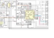 HTH Todd |
|
|
|
Post by serafis on Oct 17, 2019 13:57:29 GMT -5
Wow that's great information. Thank you so much. This is where I've got to....
I started checking for a digital signal at some of the test points, using COAX1 as input. I couldn't find anything after DIR, and SAI_SDOUT or RMCK didn't register anything either.
So I thought I'd check the supply rails to DIR. The +5v rail is fine, but the +3.3V rail reads only 384mV anywhere from the 3.3V regulator (Q746) output to DIR. Everything looks OK visually, and the rail is continuous across the various coils. The rail to GND resistance measures only around 5 ohms though.
I then removed L306, just before the +3.3V rail goes into VLS (pin 53) and VLC (pin 6) of DIR (Q301), to try to isolate the fault. The rail from the regulator to the left side of the L306 gap now reads correctly at +3.3V. Putting a meter across the L306 gap reads around 85mA. The left side of the gap (regulator side) reads around 62K Ohm to GND; the right side of the gap (DIR side) still reads around 5 ohms to GND.
The only other components to the right of L306 appear to be C319, C314 and C315, between the rail and GND. So now I'm thinking either one of those caps is faulty (unlikely) or DIR is faulty (more likely), or the regulator is faulty and unable to deliver sufficient current (possible?).
I don't know where to go from here. Any more ideas?
Thanks,
Jon.
|
|
|
|
Post by tjmotter on Nov 12, 2019 21:36:12 GMT -5
sorry for the delay in responding. You clearly have a short somewhere. I agree that the most likely candidate is going to be the DIR but the caps are MUCH easier to replace so I would start with those because they are cheap. I would also replace that regulator because it is also easy/cheap. Given that you are measuring only 5 ohms on the isolated DIR it is probably where you are going to find the fault. They are a bit of a pain to get off but chipquick will make it easier. If you don't want to use chipquick, you will have to isolate that area with kapton tape and apply heat. When I do this I typically remove all the caps in the area to keep them from getting damaged. If you have a concave tip for your iron it is pretty easy to install the new DIR. The process I use is to lay down some flux on offsetting corners, place the chip into position and apply a blob of solder across a couple of pins on one of the corners. I do this so that it holds the chip in place but is localized enough that I can reheat the area with my iron if I have to adjust the chip a little (those traces are very close together). Once everything is aligned I tack the opposite corner, check again and if everything looks aligned, I lay down some flux and use the concave tip to apply the solder to the rest of the pins. Finally, I clean up any bridges, test every pin with my meter to make sure I don't have any bridges and then reinstall the components I removed.
BTW, if you want to jump right into this, it is a GREAT time to re-check the resistance on that voltage rail after you have removed all the capacitors.
Digikey still sells these DIR's
HTH Todd |
|
srt
Junior Member
 
Posts: 90
|
Post by srt on Feb 25, 2021 2:53:43 GMT -5
I want confirm about pure audio in all Onkyo models, the analog input first going to switching ang tone control IC ,, from there its going to A/D converter IC (DIR &ADC) the sending to DSP after DAC its again going to Switching tone controller IC , is it no direct path with all bypass(ADC – DSP- DAC) , In Yamaha We are getting sound in Pure audio mode even DSP is not work , But in Onkyo , No audio out f DSP failed
|
|


