nodols
Junior Member
 
Posts: 75
|
Post by nodols on Jun 13, 2022 22:44:41 GMT -5
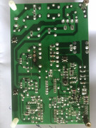
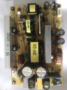
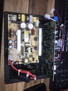
Hi All, Seems like all the experts are in here. I would like to ask anybody here who encountered this problem. Youtube doesn't seem to give any. Got a Denon 5800 for a price I can't refuse, only thing is it is dead. First it had just a red standby LED and wouldn't come out of standby. Did a processor reset, it removed the standby red LED and now I'm left with NO standby at all. No response from any buttons anymore at the front panel. Processor reset gives no response tried several times. Things I've done so far. 1. Checked all fuses with DMM - no open fuses including fuses on the mini power supply. 2. Checked switch button - ok, pressing it gives a reading on DMM, thus it is not a switch problem. 3. Mini power supply which I believe is the standby power, voltages are there on the transformer side. Mini power supply transformer has 3 voltages... - -33V VKK (which I don't know what it means) - if anyone can advice please do so. Thank you.
- -24.7 Volts for FLAC, which again I don't know what it means.
- LED +5V - read only -64.2mV - looks like this voltage is missing. (refer to attachment)
I have attached the readout in this post.
Please refer to attachment.
On CX073 7P-KR - I believe is the not so mysterious problem. Pin 1 POWER isn't giving any voltage, probably the reason why this receiver is not turning on.
That pin is from IC 802 which signals IC 801 to turn on thus turning on LED +5V, and the whole booting process.
Just wanted to know what could have caused IC802 to not giving POWER output?
Any, I mean Any input would help.
Thank you in advance.
Attachments:

|
|
|
|
Post by mastertech on Jun 14, 2022 9:37:36 GMT -5
I will look over this stuff later today and see if I can give any recommendations. Anyone else is welcome to respond.
|
|
nodols
Junior Member
 
Posts: 75
|
Post by nodols on Jun 14, 2022 18:41:14 GMT -5
I will look over this stuff later today and see if I can give any recommendations. Anyone else is welcome to respond. Hi thanks. I have all the schematics, problem is I can't upload as it is bigger than 5MB. Scratch it, I uploaded everything here: www.mediafire.com/file/j7h65q3g6iecdo3/DENON_AVR5800_JPG_schematic.zip/fileOnly problem I have is that I cannot test the whole circuit if I disassemble everything. Like when I removed the mini power supply and just tested it, no voltage came out from FLAC1 and FLAC2, when I connected everything, voltage was present. So something has turned on FLAC1 and FLAC2. Only thing is that LED+5V didn't turn on regardless if it was connected or not. |
|
|
|
Post by mastertech on Jun 15, 2022 10:23:45 GMT -5
Ok, so you have the mini power supply removed (primary unit) for testing. Look for connector cy044 and test for +6v on pin 1 , using pin 2 for your ground probe.
|
|
nodols
Junior Member
 
Posts: 75
|
Post by nodols on Jun 15, 2022 19:05:06 GMT -5
Ok, so you have the mini power supply removed (primary unit) for testing. Look for connector cy044 and test for +6v on pin 1 , using pin 2 for your ground probe. Hi, I got it connected again as it was all over the place. Anyway it is still the same voltage as disconnected or connected. Just measured it now, it is at +6.05V. |
|
|
|
Post by mastertech on Jun 15, 2022 19:58:44 GMT -5
Ok, good. So now test at CX073 pin 4 for +5v. Use pin 3 for ground probe.
|
|
nodols
Junior Member
 
Posts: 75
|
Post by nodols on Jun 15, 2022 20:36:41 GMT -5
Ok, good. So now test at CX073 pin 4 for +5v. Use pin 3 for ground probe. 0V.. |
|
|
|
Post by mastertech on Jun 15, 2022 20:50:11 GMT -5
Locate ic702 and test both sides for app. +14v. Use pin 3 again for ground probe.
|
|
nodols
Junior Member
 
Posts: 75
|
Post by nodols on Jun 15, 2022 21:17:44 GMT -5
Locate ic702 and test both sides for app. +14v. Use pin 3 again for ground probe. It's 14v on both sides, this appears to be a fusible IC. I guess. |
|
|
|
Post by mastertech on Jun 16, 2022 10:10:31 GMT -5
Are you able to test on ic802 with the unit assembled?
|
|
nodols
Junior Member
 
Posts: 75
|
Post by nodols on Jun 16, 2022 12:47:14 GMT -5
Are you able to test on ic802 with the unit assembled? It's currently assembled, I will be able to test it. Yes. I tried going to the front panel to check on the unit, the segment display had some cold solder, resoldered it and still the same. No response. |
|
|
|
Post by mastertech on Jun 16, 2022 13:30:51 GMT -5
On ic802 I need you to test voltages on pins 44 , 45 , and 10
|
|
nodols
Junior Member
 
Posts: 75
|
Post by nodols on Jun 16, 2022 23:11:32 GMT -5
On ic802 I need you to test voltages on pins 44 , 45 , and 10 Hi, Pin 10 - 5V - I guess protect is on. Pin 44 - 4.5V Pin 45 - 45.5 mV |
|
|
|
Post by mastertech on Jun 17, 2022 10:27:46 GMT -5
I believe that +5v on pin 10 is correct for not being in protect.
Somewhere probably near ic801 should be a dip switch assembly, S801. If so, locate the switch for 5-1. Switch it on and then plug in unit and see if it turns on. If it does not turn on, see if you have +5v volts on pins 1 and 4 of CX073, again using pin 3 for ground probe.
|
|
nodols
Junior Member
 
Posts: 75
|
Post by nodols on Jun 17, 2022 13:14:09 GMT -5
I believe that +5v on pin 10 is correct for not being in protect. Somewhere probably near ic801 should be a dip switch assembly, S801. If so, locate the switch for 5-1. Switch it on and then plug in unit and see if it turns on. If it does not turn on, see if you have +5v volts on pins 1 and 4 of CX073, again using pin 3 for ground probe. The 5-1, on S801 when I switch it to on position, makes a lot of relays click, as if turning on, however the front panel does not light up, and no standby LED, and if I press the power button, there is click response but I feel like the protect kicks in and no more responses after that. Even if I turn the power outlet off and on again. If I leave it at that position, 5-1 in the on position. I smell a bad burning smell, and at one point I somehow saw smoke coming out, not so much just barely noticeable. I feel like the protect kicks in before the front panel lits up, or I don't know maybe a short somewhere draws all the power thus no front panel display. I tried locating where the smell came from, but can't really pinpoint but it probably is on the other side of the board as this is two sided board. I can't pinpoint the exact location where it is getting hot or that smell comes from, but I immediately turn off the switch and the power to not leave it at that position for fear of damaging more parts. I have done this a couple of times already and there is always that smell everytime. I hope I am not damaging parts more and more everytime. |
|


