|
|
Post by gjaky on May 16, 2014 12:13:56 GMT -5
Not much activity here lately, so thought I throw in a teaser... So I have this performance issue with my NEC XG-1351 since I got it. While the machine is phisically working but I'm pretty sure something is wrong with it. The bandwidth performance of the neckboard is very bad, it's not just bad, but also makes discoloration faults with hard edges. For a quick comparision look at the picture below, that pg xtra is also mine, and while the XG wasn't dialed in that sharp when I took that picture, but it's still easy to see that it is nowhere near in resolving the vertical lines to the older and inferior PG xtra... And of course everything else was the same in the signal chain.  And a picture for discoloration:  This is also something that was unknow with the trusty old PG xtra. I spent already many hours with tracking down this issue, and found out that if I fed the neckboards directly from the PC's VGA output I got the same result (the neckboard is expecting 0,7V/75 Ohm signal too), meaning whatever happens it's happening on the neckboards. All colors are doing this quite similarly, so it seemed to be highly unlikely to have a similarly defective neckboard on all three tubes, but never mind I bought two spare boards for sure. Now I tried one of them and not surprisingly the "new" board is acting the same way, so it's really not the board itself. Then what? |
|
|
|
Post by gjaky on May 16, 2014 12:44:00 GMT -5
Let me summarize what can we know about the board. I attach the schematic diagram for the signal chain and a circuit info for the neckboard. The circuit info doesn't mention but there is an adjustable peaking circuit (driven by the System board, APT1-3 signals). There is no information how this adjustable paking is working in terms of combinations, but I already found out that the all driving lines are working and they are affecting the peaking, so I guess they are ok. As you can see the CXA1709P gets the clamping signal (CP3) directly from an outer source (the GAIN CTL board), I haven't measured this signal yet, but while it should affect the sharp edge discoloration issue, I don't know how would this affect the bandwidth thing. Besides these two things the neckboard gets its signal input, the supply voltages, there is a control line for the gamma correction (?) circuit (GM) but this circuit is only populated on the green neckboard, while the problem is present on all boards as stated above, and lastly the board has a beam current output. That's about its interface. The output is the CR tube ofcourse, but again I highly doubt there would be a similar problem with all three tubes at the same time, still I took a look at the pins of the green tube and it is nice and clean. Any thoughts and suggestions are much appreciated. |
|
|
|
Post by gjaky on May 22, 2014 14:23:39 GMT -5
Had little time, but measured the clamping signals and they seemed fine to me. Checked on the suply voltages for ripple, but again nothing. It seems I'll have to check on the neck board on the bench. That will take some time...
|
|
|
|
Post by mastertech on Jun 3, 2014 20:14:31 GMT -5
Please update if you find anything.
|
|
|
|
Post by jeremy on Jun 4, 2014 12:10:43 GMT -5
This is interesting to know as I have had some "concerns" with image quality on my XG1100. I don't have this specific problem thankfully, but I do have one problem that has bothered me since I got the projector. Something with the blue tube... I'd have to start a thread of my own and take pictures to show exactly what I mean, but if I could ever remedy the problem, I would probably fall in love all over again with the XG, other than that issue, it is one hell of a projector to watch!!
|
|
|
|
Post by gjaky on Jun 5, 2014 4:28:39 GMT -5
Sure, I just had a very important exam to pass and had little time for fun things...
Actually the signal path in the XG1100 is more based on the 6/9 PG xtra's signal path, with the XG ...1 models they completely redesigned most of the RGB circuits.
Lately I drew some color test patterns, because I found out that the color shifting problem is dependent of the content material too, so it's more and more seems to be a clamping issue. The details aren't worked out yet, but it looks like if there is a bright content on the picture's left (not quite at the edge but more like in the middle of the left side) then there looks like too much peaking in the middle (screen center), without bright content in the middle-left there isn't much peaking in the center, the right side however never peaks too much. I've tried several timings so far and I couldn't get rid of this yet.
|
|
|
|
Post by gjaky on Jun 7, 2014 15:28:26 GMT -5
I reviewed the discoloration problem, take this: it's all about therelative distance of the bright objects from the fast edge. if the hard edge is in the center the discoloration is really occurs in the middle left, if it gets closer the dicoloration wanishes, if it's farther also. However, if the hard edge is on the right, the bright area must be in the middle. That's it.
Now here is the more interesting part! I finished my test power supply so I could measure my original green neckboard on the bench. I was quite surpized to see that the Cathode output at the CRT socket is much more distorted than the G1 output. Furthermore the discoloration/overpeaking issue can be seen on the oscilloscope! It's only happening in the Cathode amp. Checked the signal path, the output from the Cathode daughter board is still good, going to the Q7901 and on it's emitter the signal gets distorted, (on the G-1 side it's all perfect) the discoloration issue can't observable there, the difference between the two amps are the Cathode amp has the adjustable peaking circuit populated, and has the output current monitored. So these are the main suspects now. It's quite late here now for further invesgitagion, hope will find some spare time tomorrow for this!
|
|
|
|
Post by gjaky on Jun 8, 2014 11:56:16 GMT -5
Here are some shots: A video of the overpeaking issue: At the Cathode output: 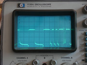 At the G-1 output (inverted): 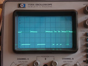 Cathode side preamplifier output (POTL1): 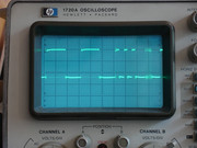 G-1 side preamplifier output (POTN5, inverted): 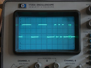 Q7901's emitter: 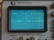 Q7913's emitter (inverted): 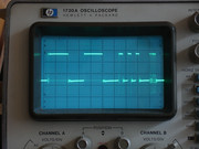 |
|
|
|
Post by gjaky on Jun 9, 2014 7:56:08 GMT -5
Success -sort of! Today I tested the second neckboard on the bench that I bought as a spare. This one was meant to be a Red CRT amp, without the gamma circuit populated. I waited so long because this one was damaged during the long journey, and two leg broke off from one of the VPJ13S', I repaired it but as it turned out today there was still something wrong with it, the bad IC had twice the gain, but basically got the same signal shape as with the other board, even at Q7901's emitter. So I decided to try one VPA13 ic instead, this solved the distorted poor quality signal immediately at the output. The peaking issue was still there though. I improved the grounding connections to the peaking components and removed the switching transistors for the switchable peaking, this solved content dependent overpeaking issue! I still have to sort out which grounding modifications have real importance and still have to test a few videopacks to see if really every VPJ13S at the Cathode has a problem with its performance. This board however has inheritently worse bandwidth than the green one I played yesterday, the 1:1 pixels are not quite well resolved even at the preamplifier output, and the VPA 13 worsen this a bit more. All measurements were made at 800x600@75Hz output. At the Cathode output 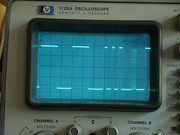 At the Cathode preamplifier output: 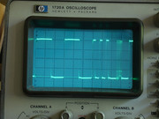 |
|
|
|
Post by mastertech on Jun 9, 2014 11:16:33 GMT -5
Great work! Keep it coming.  |
|
|
|
Post by gjaky on Jun 13, 2014 15:11:42 GMT -5
So, I pulled out all the neckboards from the XG with the hope I can make at least two fully working neckboards and leave the semi working for the blue (only removing the adjustable peaking). I tested all of those boards they really had the exact same problems as my first board. So decided to salvage the G-1 video amp from the green neckboard (which also was buyed for spare, but after I swapped this with the original board the problem remained the same). So put that IC in the place of red's K amp, and guess the problem remained still. So this f***ing b**ch IC went wrong during the transplantation, or still something else the problem... but what? I removed R7914 (68 Ohm) so only the feedback is looped back and the two diodes are there, without the feedback there is no output, I also removed the two diodes too, so there isn't much left other than the output IC. Will upload pictures about the distortion it makes, that's also an interesting thing.
|
|
|
|
Post by gjaky on Jun 14, 2014 2:19:04 GMT -5
So here is how the distortion looks like in close up. The upper trace is the VGA out, the second is the VPJ13S' output pin. Attachments:
|
|
|
|
Post by gjaky on Jun 15, 2014 4:21:26 GMT -5
These boards are beyond me, I am totally puzzled. As I've ran out of "working" VPJ13S' yesterday I've spent many hours to work out a mounting method for the VPA13, VPA15H ics from which I have more. So replaced the "wrong" VPJ13S at the red's K amp with a VPA13, and later with VPA15H and they turned out to be much worse than the original VPJ, while the output isn't distorted as with the VPJ but when the input goes from (long time before) high to low, the output transition lags 140ns(= 3pixels at 800x600 75Hz)!!! If the input is more like 1:1 on/off the lag is almost isn't present at all, but the bandwidth is still less compared to the G-1 amp. On the other hand the low to high transitions are happening immediately on the output. Now I begin to wonder how lucky I am because I could make one board work flawlessly!  |
|
|
|
Post by gjaky on Jun 15, 2014 15:44:12 GMT -5
Ok, I give it up for now, too much time, too little gain... I tried the boards in the machine, the green supposed to be fully functional and high performance, the red K amplifier is running on a VPA15H the G-1 is the standard VPJ13S, this has the lagging response, neither board shows any improvement in bandwidth compared where I started, in fact they look identical on screen. However, the discoloration issue really disappeared at least, and probably that had more impact on image quality than the bandwidth, but still I am very disappointed by the fact that I wasn't able to solve this problem.
|
|
|
|
Post by Casethecorvetteman on Jun 21, 2014 4:09:42 GMT -5
Hi Gábor, i havent had a chance to read all this yet, but i will soon. Ive been rediculously busy here lately.
Did you end up trying to feed the RGB straight to the neckboard?
|
|