|
|
Post by hulio on Mar 13, 2019 19:04:53 GMT -5
Hello Setefano, I can borrow you a good working controller if you wish, just to see if yours is at fault. You'll have to pay only the shipping costs. I really can't miss him (is my spare controller), so you'll have to send him back.
Send me a PM with your address, in case you agree.
Cheers, Stan.
|
|
|
|
Post by hulio on Mar 10, 2019 13:36:08 GMT -5
You can't, without trying another controller. Swap it with the one from the spare 909.
From the pictures of your controller it seems that those trimpots lost their sealing (red varnish) and drift. Even with a very good oscilloscope and the service manual, is not an easy task to tweak them back.
Try another controller.
|
|
|
|
Post by hulio on Mar 2, 2019 3:22:54 GMT -5
Could be that the 9V supply is dropping. C450 and C451 electrolytic capacitors from SMPS sub-board R763142S should be replaced (from 470uF 25V to 560uF 35V). There is a Barco FSB about this hanging around here.....
Try the other SMPS from your spare 909 and see if behaves the same.
|
|
|
|
Post by hulio on Feb 27, 2019 7:01:20 GMT -5
Hello Robin,
Nice project. I still have a spare SEMU II- Advanced (R7629482) for you.
Send me a e-mail with 909 stuff you can miss and think is worth trading. If i'm not wrong, you also need the CM board in order for SEMU to work (i have it as spare too). Do you already have the special connector in the convergence tray for the SEMU ?
|
|
|
|
Post by hulio on Jan 8, 2019 13:56:23 GMT -5
Hey Robin,
Some years ago, I had to upgrade my BG808 with newer style convergence driver R762518, the mini-board R762714 and software version 6.32 in order to get seagull and left side adjustments in the menu.
|
|
|
|
Post by hulio on Dec 27, 2018 18:22:51 GMT -5
It seems the boards are alright but there is a chassis/connection problem. Disconnect and reconnect all connectors (on both sides) of the extension board R763637. Is where the big black hose from the optical unit connects with the electronics unit (see page 26 of installation manual, J1,J2 and J3). Also, take care that the jumpers on that extension board are set like in this pics: 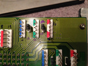 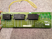 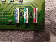 Pictures are courtesy to Francisco, from his former BR909 SP. If still no avail, could be a grounding issue too. Try another 220V outlet, from an isolated source... |
|
|
|
Post by hulio on Dec 20, 2018 1:53:00 GMT -5
|
|
|
|
Post by hulio on Dec 19, 2018 18:29:29 GMT -5
Robin, both versions (R763125 and R7631255) should be there for download. Here the newer controller schematics: New controller.pdf (919.73 KB) Yep, your split-pack is a non standard version. If a projector's part number starts with 90xxxxx, is a standard version. If 92xxxxx, it means non-standard (modified to customer requests). What is modified, you never know. Some were equipped with a fast refresh green tube, others with 90 degree turned tubes, etc. And yours obviously have a 15 pin VGA connection for port 3. Before trying another controller, I would try another source. Just to be sure. Wow, 33K hours on the chassis ? They were built like tanks, something you'll never see on consumer market. |
|
|
|
Post by hulio on Dec 19, 2018 7:51:12 GMT -5
Port 3 shouldn't be standard VGA 15 pin. It's a DB9 (9pin), here the connections. Port 3 config.pdf (93.74 KB) If your 909 has a 15 pin connection, could be that it's a SEOS 919 modified machine. Tell us more about your video chain (source, cables, scaler, Moome box or HDFury etc). Getting a sync @72hz is usually not a problem for a 909, but it depends on many things. Because the pixelclock is getting high, is more a limitation in the source. Also, unlike other Barco's, where going into high-scan mode was done by pressing some switches, the turn-over point on a 909 is done trough the menu, with the RCU. Anyway, get rid of that shaking first. If you try another RGB input board, swap the RGB driver as well. Which software version does your 909 have ? |
|
|
|
Post by hulio on Dec 18, 2018 3:25:25 GMT -5
Hello Robin and welcome.
As I understood that not all spareboards are in your possession (and sometimes, swapping boards is the fastest way of troubleshooting), let's try to solve the problem by eliminating other causes.
I see you are using a genlocked pattern. Do you get the same shaking with internal pattern as well ?
Also, which input are you using on your Barco ? Try both, ports 3 and 5 and see if the instability persists. Could be a connection/cable problem as well..
About the max. horizontal amplitude (P700 on SMPS). Don't be blinded by that 69V adjustments on a 32KHz signal. The usual way is to put the width at about 90 with the RCU and than adjusting P700 till it fills the desired width for your screen. But....don't forget to check the 17V rail again, afterwards. The Mosfets drive pulse amplitude from the horizontal board are very dependable on the 17V supply. Adjust P1 on SMPS for a 17,3V reading.
Also worth to check is the driver voltage, in the random access menu. Should be set to minimum.
Just curious, why would you want to watch @48hz on a 909 ?
|
|
|
|
Post by hulio on Jul 22, 2018 21:55:42 GMT -5
If either of those fuses are blown then the green leds on the G2 board for those 2 lines would be off, correct? (-9v and +30v) Yep, according to Barco, when F201 is blown the following leds on G2 board should be off: +CON, 30V, D120 and HDHT. When F207 is blown, led -9V is off. |
|
|
|
Post by hulio on Jul 22, 2018 17:04:04 GMT -5
A fuse that is not mounted on a fuse-holder (to be fast checked/changed by the end user), but soldered directly on the PCB.
|
|
|
|
Post by hulio on Jul 22, 2018 16:35:57 GMT -5
Other situations that will generate a scan fail red led (excepting EHT, quad and splitter) are:
1. Some unserviceable fuses on the SMPS are blown (F201, F207).
2. You have a bad CRT (shorted).
So first, try another SMPS module. To check the CRT's, with the projector turned off, disconnect the HV lead of the tube from the splitter (check the tubes one by one) and start the projector. If the scan fail led on the EHT stays off without a CRT connected to the splitter, that tube is bad. Careful, don't disconnect the HV lead of the quad from the splitter.
If you have spare parts, swap the vertical and horizontal boards too, before checking the CRT's.
|
|
|
|
Post by hulio on Nov 27, 2017 13:57:46 GMT -5
Alright, thanks for advice. I'll do that soon and report back.
Funny thing, none of four boards function like it should.....
|
|
|
|
Post by hulio on Nov 27, 2017 10:56:53 GMT -5
Yes, I meant pins 1 and 2 of the AD7416 chip.
At the harness I get on both, pins 1 and 2, a 4,2V dc reading. Of course, 0V dc on pin 3.
|
|


