nashou
Unmoderated Off Topic
Tech in Training.....
Posts: 1,239 
|
Post by nashou on Mar 23, 2019 21:18:47 GMT -5
Ok, replaced the original filter cap. left the resistor and cap to GND connected . It has been playing for about 30 minutes and the amps are not even getting warm?!?! Is that suppose to be ? I figured they'd get at least a little warm. about 85-88° Also i hardly have to raise volume for it to blast and it distorts obviously from being over driven. Volume is pretty clear only at about 8 O'clock and its minimum is between 6 and 7 . At 9 O'clock its pretty loud but still clear. I think this time its the preamp section . This is with auxiliary and the phono sections and tuner. So I ask, how important is the bias voltage for proper sound quality, I assume very. Do you think maybe 5 mV's is too little and maybe bump it up ? How would I test this? I read this Article and found it interesting. Tomorrow I may try to raise bias. How can I figure out the bias of these transistors with the data we have from the data sheets, or is that not possible? Athanasios. |
|
nashou
Unmoderated Off Topic
Tech in Training.....
Posts: 1,239
|
Post by nashou on Mar 23, 2019 14:06:15 GMT -5
Ok, here's the thing. Even though you are reading DC voltage on the speaker connectors it is (phantom) voltage. Because of the cap in series there is not a direct connection to the DC line voltage on the out line. So there is no DC current at the speaker connector which is why as soon as you connect something to it all is gone. I would think those resistors on the relay board should take care of this phantom voltage but your still get a reading. This is why i asked if you had another volt meter to test with because some meters will act different then others. So altho I am not thrilled with what your meter is telling us it appears after all your test that it should be ok to run the amp like this as long as the sound output is good. Again, this could be just your meters but there is surely no DC current there because of those caps. Maybe hook it all up and play something for a while and see if the speaker coils get hot. Just not to much bass as this may heat them up somewhat normally. Would an analog meter be better for measuring amp designs like this? I need to add one to my equipment list as some times they come in handy compared to Dmm's. Nashou |
|
nashou
Unmoderated Off Topic
Tech in Training.....
Posts: 1,239
|
Post by nashou on Mar 22, 2019 22:16:40 GMT -5
Mac, I found this post over on AudioKarma. I think that this amp is the same as what this member is taking about. 15v DC on the speaker outputsHe is stating that you test the DC offset with a load connected. And he mentions the Amp that you used for the schematic earlier, the Marantz 2230 . What say you? Nashou |
|
nashou
Unmoderated Off Topic
Tech in Training.....
Posts: 1,239
|
Post by nashou on Mar 22, 2019 21:54:09 GMT -5
You can try the 500 ohm ones but the DC may go up instead of down. But see what happens. Yeah it went up to where it was before . This is with your resistor and cap and the added 500 ohm resistors on the relay board. Would going down in resistance on the relay board reduce it then? I think I'll go back to the original resistors and then we can play with the values of the resistor on the Neg cap legs of the caps maybe? One more thing. What would cause the DC to go down after I accidentally short some pins on that socket while probing ( orange to yellow I think)? The relay clicks off then back on and DC at output is way down , but slowly climbs and eventually after lots of time back to 3 and 5 volts dc. |
|
nashou
Unmoderated Off Topic
Tech in Training.....
Posts: 1,239
|
Post by nashou on Mar 22, 2019 20:41:46 GMT -5
You can try the 500 ohm ones but the DC may go up instead of down. But see what happens. Why would it go up? |
|
nashou
Unmoderated Off Topic
Tech in Training.....
Posts: 1,239
|
Post by nashou on Mar 22, 2019 20:17:04 GMT -5
Another thing I noticed is the two red AC detecting lights on my DMM no longer light up when close to the chassis as before.
Before they would always be on unless i touched the chassis. So something is fixed on that front.
Nashou
|
|
nashou
Unmoderated Off Topic
Tech in Training.....
Posts: 1,239
|
Post by nashou on Mar 22, 2019 20:10:11 GMT -5
Try what ever you like. This is all experimental. Should be no harm with any of these options. Ok I tried your idea , 10 ohm and a .047uf cap ( all I have are Wima film ) and DC went down maybe a 1 to 1/2 VDC at speaker outs. So it helped a little . Also this time the voltage at the Neg Cap leg is equal to voltage at speaker outs . Before it was much higher I think , like 6 volts at neg cap leg . So it went down a bit. What needs to increase ? the resistor or cap value? Or should I try those 500 ohm 3 watt ceramic Ohmite resistors I have on the relay board This side was up to 5.xx vdc now its lower 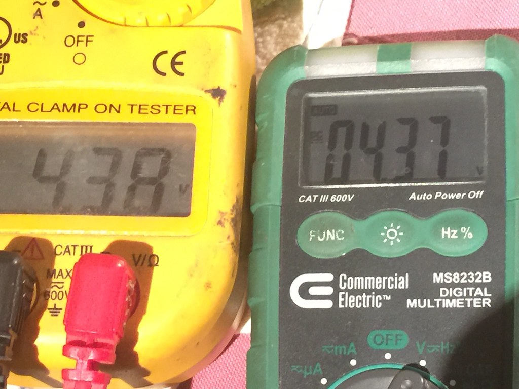 |
|
nashou
Unmoderated Off Topic
Tech in Training.....
Posts: 1,239
|
Post by nashou on Mar 22, 2019 7:23:55 GMT -5
I'm going to be signing off for the night soon so if you wanted to try just the resistor and cap Put it after the cap there now. You could solder right on the neg leg of your filer cap and then to gnd. Do the 10ohm/.5watt resistor and the cap should be around .047uf/50mw mylar if you have one. Sounds like a plan. But what If i first try increasing the 220 ohm resistors on the relay board with those 3 watt 500 ohm Ohmite resistors I have first? today is one of my long days here at The Odyssey so wont be home till about 8pm to try. nashou |
|
nashou
Unmoderated Off Topic
Tech in Training.....
Posts: 1,239
|
Post by nashou on Mar 21, 2019 20:53:11 GMT -5
I looked at a bunch of different schematics but of similar design and I am seeing .5 watt resistors and not big value, like 100 ohm, 47 ohm sometimes a mylar cap, sometimes not. But here is what I am thinking. After cards and card slots are all cleaned up, change pots if possible, resolder 220 resistors on relay board, monitor voltage at speaker connectors and see if adjusting pots slightly will remove DC and see if heatsinks stay cool, maybe check bias voltage after that also just to see. If still does not work right we can then see about adding more resistors and cap maybe. Is this what you mean with the resistor and cap? I have also seen the resistor and inductor used here as well. But this is in series not to GND I think what is that for?  |
|
nashou
Unmoderated Off Topic
Tech in Training.....
Posts: 1,239
|
Post by nashou on Mar 21, 2019 20:33:30 GMT -5
If i lower the Bias voltage across the emitter resistor to the 5 mV's you suggested then the DC goes to 5 with the one board and 3.4 with the other board. It is still doing this now or are you just referencing from before? Still doing it now, same as before.  |
|
nashou
Unmoderated Off Topic
Tech in Training.....
Posts: 1,239
|
Post by nashou on Mar 21, 2019 20:26:54 GMT -5
ok everything is ok with old pot back in. Wheeeooiouuuuuuu!!!!
What is an acceptable heat I should shoot for. When I go to lower the DC the heat goes up as well as the bias voltage.
If i lower the Bias voltage across the emitter resistor to the 5 mV's you suggested then the DC goes to 5 with the one board
and 3.4 with the other board.
I also think the smoke might have been some excess cleaner/lubricant fluid burning off.
|
|
nashou
Unmoderated Off Topic
Tech in Training.....
Posts: 1,239
|
Post by nashou on Mar 21, 2019 19:56:21 GMT -5
well that was almost a disaster!!! The trimpot i used wasn't enough to adjust and i was the board begin to smoke so I shut it down. the emitter resistors got really hot.
the horizontal one read 0 ohms but now that it cooled its reading ok. Not sure if I should continue to use it. I am going to put the old trimmer back on and make sure its ok
again. man that was scary!!!
Cross your fingers.
Outputs seem ok.
nashou
|
|
nashou
Unmoderated Off Topic
Tech in Training.....
Posts: 1,239
|
Post by nashou on Mar 21, 2019 19:26:09 GMT -5
Ok, these pots are 520 ohm , I have 100 ohm and 1k pots .
I also found two 3 watt 500 ohm resistors . I might be able to swap out the 220 ohm's on the relay board .
I also just swapped out one 2sc853 from o e board to the other . Just because.
|
|
nashou
Unmoderated Off Topic
Tech in Training.....
Posts: 1,239
|
Post by nashou on Mar 21, 2019 18:06:41 GMT -5
whats that on leg 11 on the right socket.? Nothing. 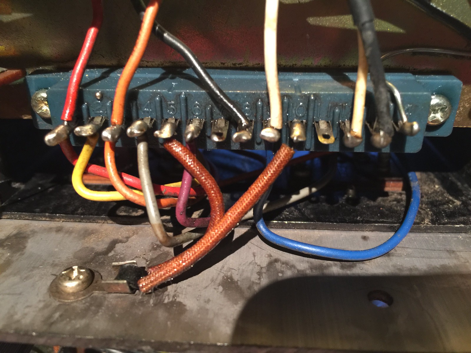 |
|
nashou
Unmoderated Off Topic
Tech in Training.....
Posts: 1,239
|
Post by nashou on Mar 21, 2019 18:05:21 GMT -5
For the pots you just measure across the whole pot, not the trimmer. but you will probably have to remove it. As far as resistors on those output lines here is what I would do. First do an ohm reading across the + and - of each speaker connector. This will tell you if there are any resistors on that side of the relay. Then do an ohm measurement from the neg side of each filter cap to gnd. That will tell you if there is any resistors on that side of the relay. let me know what you get. At speaker terminals no resistance OL , on neg filter cap pin to GND 220 ohm. Must be those resistors on the relay board. I looked I don't have any high watt resistors that are of a low value. I have some 560k and 10k 2 watters . Some smaller vales too from speaker cross overs like 7.5 ohms but 5 watts i have a lot of 1/2 watts. I could parallel them as a temp test ? Or could we use a cap as well? Nashou |
|


