|
|
Post by serafis on Feb 7, 2024 23:26:05 GMT -5
I'm trying to repair a Sony STR-DH740 that is stuck in PROTECTOR mode, and I'm stumped. Service manual is at elektrotanya.com/sony_str-dh740.pdf/download.html and schematic of SR amplifier channel attached. At first, I couldn't get it out of PROTECTOR mode, or get it to stay on long enough to determine the fault. Test Mode History showed PROT NORM which wasn't much help. After examining the protection schematic, I decided to bridge pin 92 of the MCU (PROTECT) to 3.3V, to hold it high, and that allowed me to keep it turned on for diagnosis. I found -60V DC output on the SR channel speaker terminals, with all of the other channels reading in the 1-5mV, so that's the issue. Output transistors check out OK, but to be certain, I tested them out of circuit, and even swapped them for another channel. No difference. Pin 1 (Base) of Q750 and Q751 output transistors, which should read +1V and -1V respectively, both read -60V The center pin of R753, which I think should read 0V also reads -60V. Those pins on a good channel read correctly. I used the DMM to test every component in the amplifier section for this channel (in circuit), comparing the readings against a good channel, and everything checks out exactly the same, except for one measurement, R768, 47KOhm. On any good channel, this resistor initially reads around 20K and slowly rises over a number of minutes, not sure what it would eventually get to as it's hard to keep the test leads on it for that long. But on the bad channel it immediately reads 47K and doesn't change. I removed it and checked - it's 47K out of circuit, so whatever's causing the anomaly is elsewhere. I expected to find a shorted transistor somewhere, but I've double checked every component, especially the semiconductors, and can't pinpoint a faulty one, or one that reads differently than a good channel, so I'm completely stumped now. Any ideas? Thanks.  |
|
|
|
Post by mastertech on Feb 8, 2024 20:23:55 GMT -5
Remove Q754 and test it out of circuit. If it tests ok, leave it out and check for that -60v on the previous locations where it should not be.
|
|
|
|
Post by serafis on Feb 8, 2024 21:54:16 GMT -5
Q754 (tiny SMD) tested fine out of circuit, and still measuring -58 to -59V where it shouldn't be. While disassembled, I also tested Q772, Q775 and Q774 out of circuit (they're thru-hole so easier to remove safely) and they all tested OK too.
|
|
|
|
Post by mastertech on Feb 8, 2024 22:18:54 GMT -5
Q754 (tiny SMD) tested fine out of circuit, and still measuring -58 to -59V where it shouldn't be. While disassembled, I also tested Q772, Q775 and Q774 out of circuit (they're thru-hole so easier to remove safely) and they all tested OK too. Leaving these removed what is your voltage on pin 1 of Q750 and Q751? |
|
|
|
Post by serafis on Feb 8, 2024 22:47:44 GMT -5
I had reinserted them so I'll need to disassemble again to remove them again. I'll get to that tomorrow and report back.
|
|
|
|
Post by serafis on Feb 9, 2024 20:41:09 GMT -5
With Q754 still removed, and Q772, Q775 and Q774 also removed, voltage on pin 1 of Q750 is around +16mV and Q751 around +4mV.
Still removed, approx readings from the main board are:
Q772(B)=+60V, (E)=+60V, (C)=+16mV
Q774(B)=-60V, (E)=-60V, (C)=+60V (from Q772(B) via R770, R771 and R772)
Q775(B)=-60V, (E)=-60V, (C)=+4mV
Guessing one of these transistors is faulty, but which one?
|
|
|
|
Post by serafis on Feb 9, 2024 23:40:54 GMT -5
I replaced all three with good ones salvaged from another amp. Also refitted Q754. I was hopeful, but no. Still -60V on Pin 1 of Q750 and Q751, and center pin of R753.
Q772(B)=+60V OK, (E)=+60V OK, (C)=-60V should be +1.1, i.e. same as pin 1 of Q750
Q774(B)=-60V OK, (E)=-60V OK, (C)=+60V should be 15V
Q775(B)=-60V OK, (E)=-60V OK, (C)=-60V should be -1V, i.e. same as pin1 of Q751
Then I measured Q770 (in circuit, powered up) and compared it with a good channel (which incidentally doesn't seem to match the measurements shown on the schematic)
B1 C1 B2 C2 Common E
Q770 (bad) +0.1V -60V +0.675V -60V +0.675V
Q620 (good) +0.054V -60V +.054V -60V +0.6V
Not sure what this means though.
|
|
|
|
Post by mastertech on Feb 11, 2024 18:05:23 GMT -5
B1 C1 B2 C2 Common E Q770 (bad) +0.1V -60V +0.675V -60V +0.675V Q620 (good) +0.054V -60V +.054V -60V +0.6V There seems to be a problem with your layout, (B1 C1 B2 C2 E). Can you re-verify these readings and locations? |
|
|
|
Post by serafis on Feb 13, 2024 4:02:31 GMT -5
Yes, the readings don't seem to bear much relationship with the schematic. I re-measured (several times) wrt GND (after power on and main relay click, but before it goes into protector mode and powers off again), and checked against the layout in the datasheet for HN4A06J, and this is what I get:
Bad channel: B1 = +0.111V, C1 = -58.8V, B2 = +0.627V, C2 = -58.8V, Common E = +0.667V
OK channels: B1 = +0.063V, C1 = -57.4V, B2 = +0.063V, C2 = -57.4V, Common E = +0.611V
Schematic says B1 = 0.5V, C1 = 0V, B2 = -60V, C2 = -60V, Common E = 0V
Tomorrow I will try to bridge MCU pin 92 to 3.3V again to keep it out of protect mode and measure again, but I can't see why that would change anything. Makes no sense at all to me at the moment.
|
|
|
|
Post by mastertech on Feb 13, 2024 14:15:44 GMT -5
Based on your readings I can not even assume that your "OK" channels are actually ok. At this point, if it was me, I would try disconnecting the SR channel from the protection circuit by removing some parts from that channel (not the protect circuit itself) and see if the unit stops going into protect. Once it is not going into protect and stays on, and has no DC on any outputs, I would try some channels to see if they properly output audio.
|
|
|
|
Post by serafis on Feb 14, 2024 3:20:57 GMT -5
Good idea. I have to go away unexpectedly for a few days but I'll try that next week when I get back.
|
|
madmal
Junior Member
 
Posts: 22
|
Post by madmal on Feb 18, 2024 10:53:58 GMT -5
Just a thought, the fact that on the bad channel, that resistor does not have the behavior of changing resistance over time and stays at 47k to me suggests there is a capacitor at fault somewhere not charging over time while you are measuring that resistor.
I have had a very similar issue on a Yamaha, protect and high dc volts on one output, the culprit turned out to be a 100uf cap in the feedback circuit.
Did you check c618 and c763?
|
|
|
|
Post by serafis on Feb 22, 2024 3:18:24 GMT -5
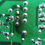
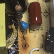
Just a thought, the fact that on the bad channel, that resistor does not have the behavior of changing resistance over time and stays at 47k to me suggests there is a capacitor at fault somewhere not charging over time while you are measuring that resistor. I have had a very similar issue on a Yamaha, protect and high dc volts on one output, the culprit turned out to be a 100uf cap in the feedback circuit. Did you check c618 and c763? I had a similar thought, however I've checked all of the electrolytic caps and they seem to be OK. I'm becoming deeply suspicious of Q770, despite it reading similar to the other channels on the DMM. So I attempted to get a photo of it to compare with the same transistor on a good channel, and this is what I saw: Bad Channel
 Good Channel Good Channel
 Looks a bit 'fried' to me, but I can't find a local stockist at a reasonable price and replacing it would be very fiddly. Thoughts? |
|
|
|
Post by mastertech on Feb 22, 2024 14:20:18 GMT -5
I see mouser has it. Is shipping that expensive to you? Many places have it here in US.
|
|
|
|
Post by serafis on Feb 22, 2024 14:51:28 GMT -5
I see mouser has it. Is shipping that expensive to you? Many places have it here in US. Yes, I saw that Mouser have it, but shipping is NZ$26 for orders under NZ$66 (free for over NZ$66), which makes it uneconomic for small orders on a "try it to see if it fixes the problem" basis. I'll need to wait until I have a lot of other stuff to order. |
|


