|
|
Post by viggen on Aug 15, 2024 21:12:16 GMT -5
Unfortunately my Yamaha RX-V771 won't power-on anymore, no relay clicking noise.
It won't even power-on when trying the self diagnostic function via "While pressing the “TONE CONTROL” and “INFO” keys, press the “MAIN ZONE ” key to turn on the power."
This is what happened, it all started with my Jamo 660 Sub not powering on anymore.
I checked the fuse and it was brown/burned. (worked for over 15 years)
By accident I ordered the wrong fuse, I ordered the T4.0AL/250V instead of the T2.0AL/250V.
In addition, as I was not looking properly I put the cable that connects the Yamaha RX-V771 into the Jamo 660 Line Out instead of Line In via RCA cable.
Then when I powered on the Jamo 660 with the wrong T4.0AL/250V fuse and the new wrong fuse in the Jamo 660 shattered.
And from that point the Yamaha RX-V771 won't power-on anymore either.
The Yamaha RX-V771 was switched off at the time when I switched on the Jamo 660 with the wrong T4.0AL/250V fuse (instead of the T2.0AL/250V).
The Yamaha RX-V771 was fully functional before the wrong fuse was put into the Jamo 660 Sub and was connected wrongly to the Yamaha RX-V771.
Does anyone have any ideas of what might be wrong please?
I'm trying to establish if the potential repairs are that significant that it is not worth me taking it to a professional electronics repair shop.
|
|
|
|
Post by dobrykamil on Aug 16, 2024 13:53:27 GMT -5
Check if you have 3.3V on on of the main power On switch. The other one is GND.
|
|
|
|
Post by serafis on Sept 29, 2024 5:15:22 GMT -5
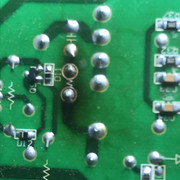
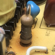
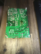
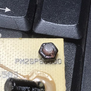
Get the service manual from elektrotanya.com/yamaha_rx-v771_av_receiver.pdf/download.html. The Power Supply block diagram on P85 may be a good starting point. I think this is how it works. When mains power is applied, the power board provides 3.3V standby via a voltage regulator (IC97) to the microprocessor (MPU) which, after conducting some basic checks, supplies 3.3V to the front panel for the standby LED and another 3.3V to the front panel for the power switch. When the power switch is depressed, it pulls that 3.3V to low, which tells the MPU to carry out further checks (e.g. basic voltage and current). If these are OK, the MPU sends a voltage back to the standby power supply via PRY, which switches transistor Q3702 to activate the main power relay (first CLICK) to provides power to the main transformer and the other parts of the unit including the power amplifiers. The MPU then checks for over-temperature, over-voltage and over-current (i.e PROTECT MODE) in the power amplifiers and if all of these are OK, after a couple of seconds it sends a voltage to turn on all of the speaker relays (second set of CLICKS). If in PROTECT MODEN, this is when you can usually use the diagnostic functions. Since there are no CLICKs at all, I'd start by checking all fuses on the power board (P102 and P120), removable or soldered, replacing any that are blown. Then look at the Digital Board (P86). First, check for any visual damage, e.g. burnt or corroded tracks, burnt, discoloured or bulging components etc and fix or replace as needed. Next, I'd apply power. Check that +5.5V is present on connector CB947/+5.5V (two pins). If not, then there's a fault with the power board or its connection to the digital board. Check that +3.3V is present on connector CB948/+3.3M. If not, check IC97 input (Pin 1 & 4, +5.5V) and output (Pin 3, +3.3V). If input is OK but no output, this regulator will need replacing. If +3.3V is present on connector CB948/+3.3M, press the Power button and see if CB948/PRY goes high. If it does, then the problem is with Q3702 or the main relay on the power board, or the connectivity between the boards. Check on connector CB81 that STBY_LED (pin 5), +3.3M (pin 6) and PSW_DET (pin 13) all have +3.3V, and that Pin 13 (PSW_DET) drops to low when the power button is pressed. Let me know what you find and I'll see if there's anything else I can suggest. |
|


