|
|
Post by cklazer on Mar 5, 2015 13:10:57 GMT -5
Hello,
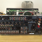
I've got a problem with this receiver that nothing is working but the LED is flashing!
No relay is clicking or something else.
Standby-Board is OK. All Fuses are OK.
I measured many transistors, z-diodes and so one...
PDOWN, P_LINE_FAIL, P_AMP_FAIL and P_CUR_FAIL are ok!!!
If I connect +5VL to Standby, the relay 701 clicks but the led is still blinking!
What do they mean with B Power Board? Is +5VDD the same as 5VD?
Please help. I cannot locate the problem.
Thanks in advance.
Greets
cklazer
P.S. I can attach the pictures from schematic...
|
|
|
|
Post by mastertech on Mar 5, 2015 16:31:58 GMT -5
Give me an hour or so and I will respond.
|
|
|
|
Post by mastertech on Mar 5, 2015 22:59:32 GMT -5
Have you read through the Marantz SR7002 thread here on the forum?
|
|
|
|
Post by cklazer on Mar 7, 2015 8:30:09 GMT -5
Hello,
yes I read the thread.
What I did is this:
- bridged the relay 701 on standby board at C792
- Measured these connectors:
DSP-Powerboard(BN38) 3: 1,2V
4: 0V
5: 5V
6: 5V
7: 5V
8: 5V
9: 0V
and BN91: 3V3
I hope you help me further...
Greets
|
|
|
|
Post by cklazer on Mar 7, 2015 8:51:46 GMT -5
Hello,
I tested the following thing:
With C792 bridged, I pressed pure direct + 7.1input + clear and now the blue leds from input selector and volume selector are on but I did not press the power button.
But display is off!
With power button, the amp goes into protect!
|
|
|
|
Post by cklazer on Mar 7, 2015 9:27:50 GMT -5
Hello,
Error seems to be on the HDMI PWB, cause if it is disconnected I get 5V on the Pin4(Standby) of BN38!
But the display is dead! Is this correct with HDMI-PWM disconnected?
Greets
|
|
|
|
Post by mastertech on Mar 7, 2015 14:03:12 GMT -5
Hello, yes I read the thread. What I did is this: - bridged the relay 701 on standby board at C792 - Measured these connectors: DSP-Powerboard(BN38) 3: 1,2V 4: 0V 5: 5V 6: 5V 7: 5V 8: 5V 9: 0V and BN91: 3V3 I hope you help me further... Greets Pin 3 voltage is incorrect. You need to go to the standby board, CN70 and get me the voltage readings there. |
|
|
|
Post by cklazer on Mar 8, 2015 4:25:46 GMT -5
Good morning,
today I powered on the SR8002 and it is in protection mode! (HDMI-PWB disconnected)
Strange...
Here are the voltages with power switch on @ CN70 (Standby Board):
P_DOWN: 5V
STANDBY: 0V
PR_POW: 14,89V
+5VL: 5V
P_GND: 0V
+12VL: 12V
P_GND: 0V
When I reset the device with: pure direct + 7.1Input + clear the voltages on standby is correct too: 5V
The rest is the same P_DOWN: 5V... and so on.
I have got a question: If I try read the service manual I think @bn38 (DSP-PWB) PIN9->HEAT should be 5V or I am wrong?
Greets
|
|
|
|
Post by mastertech on Mar 8, 2015 12:52:57 GMT -5
You indicated that pin 3 of BN38 was 1.2v
This pin is the P_Down line and should be 5v.
It comes from the standby board pin 7 of CN70.
But here you indicate you have 5v.
So you have to find out why there is a difference unless it was an error in your testing.
|
|
|
|
Post by cklazer on Mar 9, 2015 13:14:38 GMT -5
Hello,
sorry my mistake.
PIN3 of BN38 is 1,2V if PowerSwitch is off.
If powerswitch is on there is 5V.
The rest is the same:
4: 0V
5: 5V
6: 5V
7: 5V
8: 5V
9: 0V
Greets
|
|
|
|
Post by mastertech on Mar 9, 2015 22:23:12 GMT -5
Next would be to check the +/-15v supply. Check images below. Use pin 2 for ground probe and test pin 1 and 3 for -15v and +15v. Let me know what you get.   |
|
|
|
Post by cklazer on Mar 13, 2015 9:52:08 GMT -5
Hello.
sorry for my late reply, but
the +-15V are there...
Greets
|
|
|
|
Post by mastertech on Mar 13, 2015 12:08:14 GMT -5
Ok, since you found something with the HDMI board we might as well investigate it. On the HDMI board there is a connector, BN31. The +5v comes into pins 3 and 4. Now I don't know if this is a harness or direct board to board connection so you will have to determine what you need to do. But I need you to test for +5v on those pins with it connected and then not connected but when not connected, test on the connector that is NOT the HDMI board itself.
|
|