Post by dolivas27 on Jun 13, 2015 4:45:04 GMT -5
Ok looking for a little help with this one I picked up another TX-NR609 off of eBay knowing it had a bad HDMI board.
So I get the unit plug it in to test it out a bam it blows the SBR channel and I mean with a POP.
So I take the unit apart and replace the blown output Transistor and the few resistors that have blown. Put the unit back together and get ready to adjust the idling current.
I start to adjust the idling current and BAM blows the new out Transistors and now the 2SC5171 transistor also blows.
So once again I replace the parts that have blown and recheck everything again to see if I have missed anything. Everything looks goods.
Put the unit back together plug it in and I have the meter on the SBR channel as soon and I turn the unit on I see the meter start to climb so I let it run for a few seconds and then shut it down I notice that the SBR Transistor are starting to get HOT. What do you think I am missing?
Here is a list of what was replaced on the AMP Input stage.
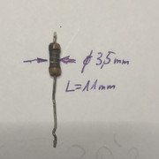
R5356 & R5366 18 Ohm ¼ Resistors
R5476 82 Ohm Resistor
Q5266 2SC5171
Q5256 2SA1930 (Did not test bad but I had them on hand so I replaced it)
Everything else around this tested ok resistors, transistors, caps from what I can tell.
Here is what I have replaced on the AMP Section.
Q6056 2SC4468 (I replaced this with a Fairchild Semiconductor FJA4310OTU)
Q6066 2SA1695 (I replaced this with a Fairchild Semiconductor FJA4210OTU)
R6106 dual .22 Ohm Resistor (This did not test bad but after the replacement transistors popped again I also replace it as I had some on hand)
Once again everything else in this circuit testing good unless I am missing something.
Do you think the replacement transistors are causing a problem? I have used them in the past without problems.
Also question on the Idling Current Adjustment for the other Onkyo Amps I have worked on it says to fit the test jig with two 100 Ohm resistors and in the service manual for the TX-NR609 it does not say anything about the 100 Ohm resistors? Are they not needed on this model or is Onkyo just assuming that we know they are needed?
One last question do you think the defective HDMI board could be causing the problem? I would think not but at this point I am just not sure. I need to fix the defective channel before I can send it back to Onkyo to replace the HDMI board.
So any help that you can provide would be greatly appreciated.
Thanks,
Dean


