Deleted
Deleted Member
Posts: 0
|
Post by Deleted on Sept 20, 2015 12:02:57 GMT -5
It is my understanding that the N/S Bow and Key are a global adjustment and are only adjustable with the green controls which then affects all 3 grids, right? Yes, correct! When calibrate geometry in the top and bottom key/bow the projector show only green because red and blue must follow the reference green. Yes but I wondered if you checked that the convergence did work at all after the rv with bv switch. If the wire does not connect than red also does not react on green. Double check! |
|
|
|
Post by Decibel on Sept 20, 2015 12:55:31 GMT -5
Tomorrow I'll shot some pictures, unfortunately I have big difficult with language.
|
|
|
|
Post by mastertech on Sept 20, 2015 13:14:44 GMT -5
Tomorrow I'll shot some pictures, unfortunately I have big difficult with language. Yes, we realize the language is a problem so that is why we are trying to work through it.  |
|
|
|
Post by Decibel on Sept 20, 2015 17:20:39 GMT -5
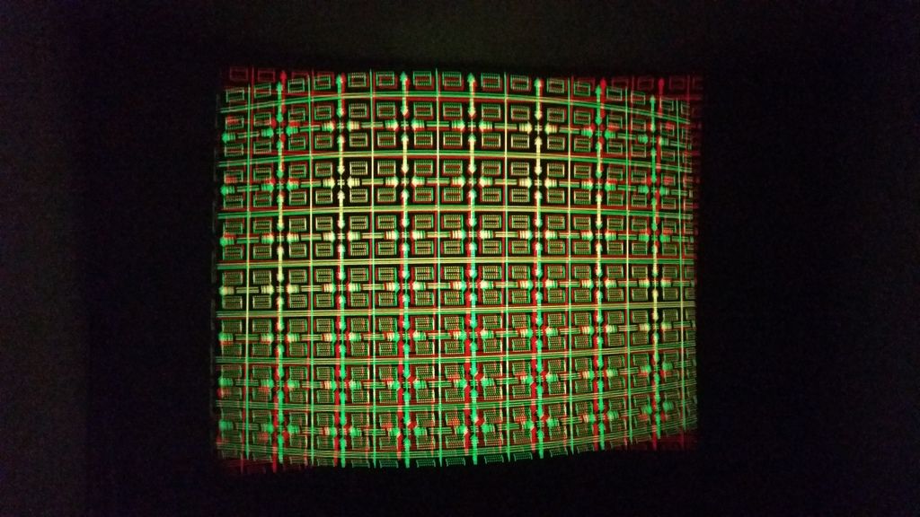
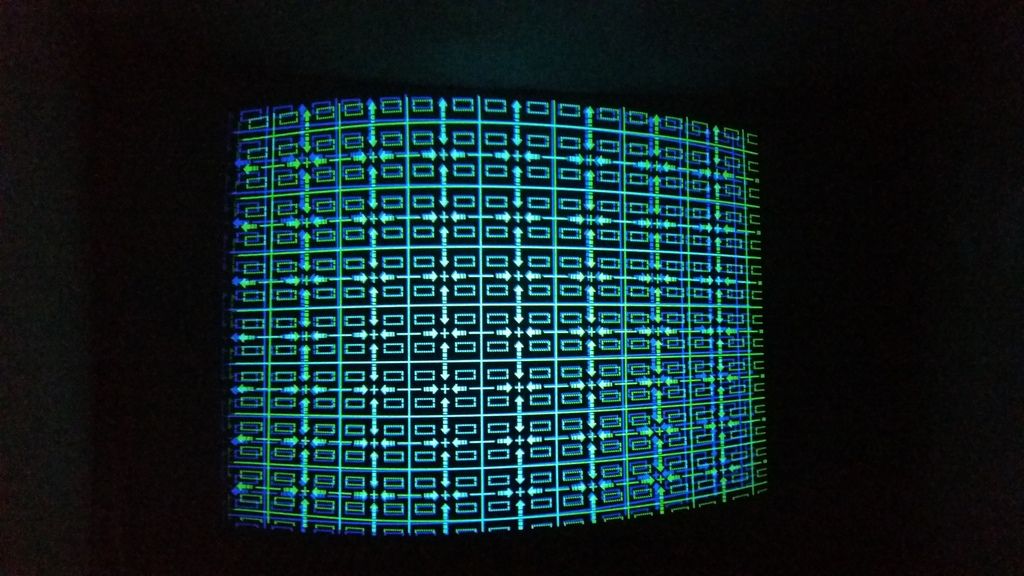
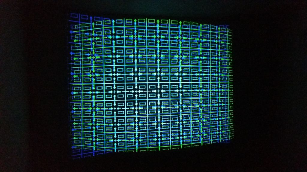
 The controller board send correct signals to convergences board. In example one, the signal BV apply correctly the N/S adjustments of blue (the BV line works). In example two, the signal RV apply N/S adjustments of blue (also the RV line works). If I cut RV line (example three) also blue lost the N/S adjustments. Example one (covered blue but it follow green)  Example two (I covered the red but it is always bad).  Example three (I covered the red but it is always bad)  |
|
|
|
Post by mastertech on Sept 20, 2015 20:17:52 GMT -5
I like your chart. It explains it very well. So the problem is surely on the convergence board.
So now we are back to this:
"With projector turned off and unplugged, disconnect J571 on the convergence board. Set DMM to diode scale. Put the negative probe on pin 6 of connector J571 and with the positive probe test pins 1,3 and 5 and give me those 3 readings."
|
|
|
|
Post by Decibel on Sept 21, 2015 2:25:03 GMT -5
So now we are back to this: "With projector turned off and unplugged, disconnect J571 on the convergence board. Set DMM to diode scale. Put the negative probe on pin 6 of connector J571 and with the positive probe test pins 1,3 and 5 and give me those 3 readings." In picture the pins of J571, please confirm the numbers that I must check. Attachments:
|
|
|
|
Post by Decibel on Sept 21, 2015 2:55:21 GMT -5
However the meter say always "1" (no react).
I tried swap probes but no change: always "1".
|
|
|
|
Post by mastertech on Sept 21, 2015 10:23:31 GMT -5
I wonder if there is another language that can better translate into your language. It would have to be translated twice but if it was more understandable to you it would be much better.
I can continue giving you testing procedures but I am afraid you may not understand what I am saying.
|
|
|
|
Post by Decibel on Sept 21, 2015 10:30:54 GMT -5
I put the negative probe to "gnd" pin 6 of J571.
Then put positive probe respectively to RV; GV; BV (1; 3; 5).
Is not correct?
|
|
|
|
Post by mastertech on Sept 21, 2015 22:35:30 GMT -5
I put the negative probe to "gnd" pin 6 of J571. Then put positive probe respectively to RV; GV; BV (1; 3; 5). Is not correct? This was correct. Now before we get to deep into this I want you to try swapping Q3 and Q63 and then with the convergence board properly connected test to see which grids move and which one does not. Do not replace these 2 transistors with new, just swap them. Let me know what you get. |
|
|
|
Post by Decibel on Sept 22, 2015 3:12:42 GMT -5
Tried ... no change
|
|
|
|
Post by mastertech on Sept 22, 2015 9:15:52 GMT -5
Ok, time to start narrowing this problem down. Take these same 2 transistors (Q3 and Q63) and remove them again. Then bend the third (leg 3) leg out and up on both enough so when you reinstall the transistors this leg does not hit anything on the board. Install the 2 transistors using 2 legs only on each. Then take 2 small pieces of wire, preferably solid core, not stranded (because stranded wire has a chance of a stray wire sticking out and touching something). Solder 1 wire from the hole of 1 transistor to the leg of the other transistor. Do the same with the other wire with the other hole and other transistor. We are crossing the circuits. Then install board and test for grid movement. This will help to narrow down where in the circuit the problem is, IF it is in this circuit. It may take us a while to find it. 2SK511 datasheet: pdf1.alldatasheet.com/datasheet-pdf/view/108824/HITACHI/2SK511.html |
|
|
|
Post by mastertech on Sept 22, 2015 9:27:15 GMT -5
.  |
|
|
|
Post by mastertech on Sept 22, 2015 9:38:33 GMT -5
I was just double checking these schematics and it looks like you have to also cross another line in these circuits to do the test properly.
This would be R4 and R64. Just lift 1 leg on each resistor (make sure it is the same leg) and use wire to cross the circuits.
I will attach image shortly.
|
|
|
|
Post by mastertech on Sept 22, 2015 9:40:59 GMT -5
|
|