|
|
Post by mastertech on Jul 5, 2015 14:14:29 GMT -5
Will you forget about that for now and get back to that ++9v testing.  |
|
|
|
Post by Decibel on Jul 5, 2015 14:29:54 GMT -5
I do not understand why remove the SR4. Would not it be easier to try to test if the voltage ++9v exists from SMPS sub board?
If the ++9v does not come from the SMPS sub board, will not even on the controller.
Correct?
The good new is that - perhaps - the issue is not in the controller.
|
|
|
|
Post by mastertech on Jul 5, 2015 14:35:49 GMT -5
The ++9v will be the same as it is now regardless of where you test at. The circuit must be broken somewhere to determine which boards the problem is on. SR4 is the most logical place at this point, especially since you have tried a different SMPS and had the same results. You can do as you wish but I am starting to feel like I am banging my head off the wall here and will soon drop out of the conversation is you do not start doing logical tests instead of waiting on some magical solution to just appear.  |
|
|
|
Post by Decibel on Jul 5, 2015 14:48:41 GMT -5
Not a problem for me remove the SR4. I'm very very grateful at anyone helping me, but I would like to understand what I'll could discover doing this thing.
In short, if the module SMPS is working properly and provides ++ 9 at controller, what happens if remove the SR4?
|
|
|
|
Post by mastertech on Jul 5, 2015 15:05:48 GMT -5
Oh, you want an explanation. Ok.
Right now you only have 2.8v at SR4. Now this means 2 things. Either the SMPS is not producing the full 9v "OR" the SMPS is working properly and a partially shorted component somewhere on the 9v line is pulling the voltage down to the 2.8v that you are reading.
So you now need to find out which it is. The easiest way to to start disconnecting boards the 9v feeds while rechecking the voltage with your meter to see if it comes back up to full or not.
Fortunately the 9v line does not feed a lot of board. The only other thing I saw the 9v from the smps feed was the on light diode. So now if the voltage comes up to normal with SR4 removed then the problem is on the controller. If it does not come up then we have to look at this on light circuit and if that is ok the we are down to the SMPS. But no sense just randomly hunting around to we start with SR4 as a good divider to know where to look next.
|
|
|
|
Post by Decibel on Jul 5, 2015 15:37:17 GMT -5
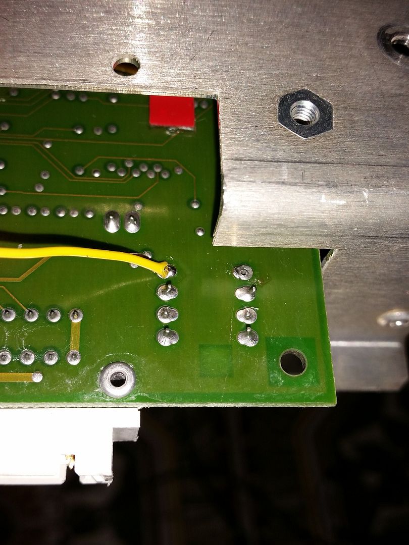
Oh, you want an explanation. Ok. Right now you only have 2.8v at SR4. Now this means 2 things. Either the SMPS is not producing the full 9v "OR" the SMPS is working properly and a partially shorted component somewhere on the 9v line is pulling the voltage down to the 2.8v that you are reading. So you now need to find out which it is. Ok the SR4 was removed. The test wire is ready.  |
|
|
|
Post by mastertech on Jul 5, 2015 15:53:38 GMT -5
And the test wire is on the pad that goes to the SMPS? testaway.  |
|
|
|
Post by Decibel on Jul 5, 2015 16:02:38 GMT -5
I did not understand very well. What is the SMPS pad?
|
|
|
|
Post by mastertech on Jul 5, 2015 16:26:55 GMT -5
Each point where SR4 is soldered is a solder pad. So it has 2. 1 goes to the SMPS direction and the other goes to the regulators mounted on the controller. You want your wire soldered to the pad that goes to the SMPS direction. Is that better?
|
|
|
|
Post by Decibel on Jul 5, 2015 16:49:29 GMT -5
Ahhhh ok
Yes that pin goes to SMPS, the other pin goes to C225 on controller.
|
|
|
|
Post by mastertech on Jul 5, 2015 16:55:33 GMT -5
Ok, good. So put controller back in, connect your volt meter and turn it on and see what you get.
|
|
|
|
Post by Decibel on Jul 5, 2015 17:20:25 GMT -5
Just tried checks, the results below.
All tests without HV board as suggest by dummyload.
With My SMPS = 3.8/4.00 v
With other SMPS = 3.4/3.8v
Then reinsert my SMPS and tried to pull Vertical board = 3.8/4.0v
Then I tried to pull also RGB input/driver boards (only SMPS and Power corrector present) = the Projector won't start.
Then reinsert Vertical/no RGB input/driver boards = 3.8/4.0v
|
|
|
|
Post by mastertech on Jul 5, 2015 18:22:19 GMT -5
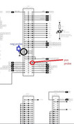
Ok. Follow these next directions carefully so we can get this narrowed down. This test will be with projector NOT running and UNPLUGGED. Remove SMPS. On the mother board where the SMPS plugs in locate J421. Set your multi meter to diode scale. Look at attached image and test between these 2 point and give me your meter reading.  |
|
|
|
Post by Decibel on Jul 6, 2015 0:56:36 GMT -5
Ok. Follow these next directions carefully so we can get this narrowed down. This test will be with projector NOT running and UNPLUGGED. Remove SMPS. On the mother board where the SMPS plugs in locate J421. Set your multi meter to diode scale. Look at attached image and test between these 2 point and give me your meter reading.  The meter said "1" Bingo? |
|
|
|
Post by dummyload on Jul 6, 2015 2:11:20 GMT -5
No not bingo yet, please stick to what we ask you to do, i never suggested pulling vertical board or rgb board and by the way pulling the hv board has nothing to do with finding the cullprit but is for safety (tubes and you, see removing vertical board) because you don't need hv anyway at this stage, remember that al the software driven protections or out when the ++9v is at +3v the core of the controller is not running. So back to the point ,with removed sr4 does the main power supply still goes on or is the set in stby now ?If it still goes on remove the front tray of the projector it should come on in standby now (no jumper at subboard smps) ,measure again the ++9v on the motherboard remote fiche .With removing the front tray (controller board ) you are 100% shore if it's the controller board because there still can be a short at the connector .
|
|