Post by dreams9661 on Oct 13, 2015 10:27:37 GMT -5
Hi All,
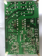
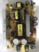
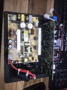
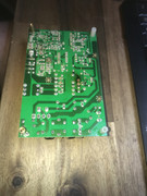
I'm in need of assistance in repairing my PFC board. After years in storage, it has come to that stage where i need to put these things together and finalise it once and for all. And so let us begin...
The 3 fuse had blown off once i turn on the set. Ok, here is what i've found out.
1. The Ntc1 on the primary section had a crack on it. So i replaced it with the same which is Ntc 22.
2. I recapped all the capacitor according to uF and voltage rated accordingly.
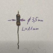
3. The resistor, they looked char/darken but still hold the same value. So i decided to replace them just incase they would fail along the way. Question? i've read else where that these
resistors are not the normal type resistor. Some what fusible resistor? Can someone shade some light on this PLEASE.
4. Tested the Bridge rectifier - D20XB60... Aussie current falls between 220V - 240V. ( Initial test i was getting was high 253V. I didn't want to ended up coming back so i replacement them
anyway).
5. Replaced D101,
6. Replaced Q100, Q101, Q103 ( Original part 20N60S5 replaced with fairchild FGH20N60SFD can admin please help double check if i was using the correct ones. Q103 was one that
took down the F3 fuse.
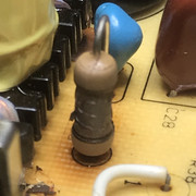
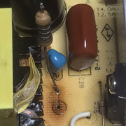
7. C101, C113, C112 metal oxide caps 100n mox? The Mrs says they look like the yellow corn kernels... I said "This is what they have for breakfast" lol ( I need to replace this they look
unhealthy. Can admin locate these components. Thx)
8. L101 and L102. These are the inductor. I have the blue Q ring tester from Anatek Corp. Im getting no reading on both of them. On Dmm there is connectivity. Question. Should i replace
them?
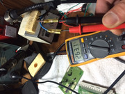
9. On the main capacitor C106, C107 and C108 testing with main power on, the filter capacitor point i was getting was 330 vdc. In my opinion, it should be ok.
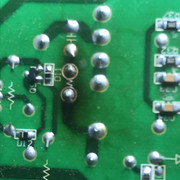
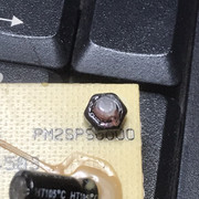
Here is why i got distracted, upon desoldering the ptc1 and ptc2 because of this things are tiny, i get to the point where i snapped the hood and the ferrite beads inside broke into pieces... You know the village where i came from, even the donkey hang their head in shame.... thats how bad my day was.... Anyway, another day another dollar.
I've dragged it far too long now, i've got 2 months of grace. My counter attack is, i need to finalize by getting this parts but i haven't got the resource to get them.
1. Sr1 resistor
2.PTC1 AND PTC2 ..... ( using jumpers? that defies the purpose of the Input protection and Emi Filtering circuit. Let's try to avoid Jumper at this stage)
3. UC3708N - I need to find the vcc pin on this power ic. Its been long gone i left my brain else where? Vcc pin will tell me how healthy is the primary side of the board.
4. Wasn't there any replacement part for Q70 bulletin a while ago?
5. How to test C115? what is the correct value. I can't seem to read them clearly.
6. SMD - Ok i need help here. This is not where my forte is.
I need to inform you guys. Before i got distracted, I did a light bulb series test. For inexperience readers, it means instead of using fuses on the F1 and F2, i substitute them by using 100w bulb connected at each end of the terminal. Reason? Great way to diagnose a set without damaging any parts you've replaced. At the start it was waaaaay bright. After replacing those parts,
once power on, light bulb went bright and slowly dim but not fully off.
Admin, and friends, first of all i thank you for your patience and participants in helping me. My electronic skills is limited to what i've learn in school. Im 36 years of age, I should have pay close attention to my teacher instead of the hot chick whose got rock size melon sitting adjacent to me. Im terribly sorry. I let you guys down. hahahaha i'm just having fun guys cheer up...
Thanks in Advance
Anthony
p/s I'll work on the Smpower supply. To get myself an early start...


