|
|
Post by thespianator on Oct 20, 2015 18:38:11 GMT -5
I acquired a Jamo Sub 300 as a throw-in with a couple of speakers, was told it worked, and it has sat around for quite a while until I decided to check it out. It kept blowing fuses, so I pulled the plate amp out to see what I could see. The amp was already disconnected from the driver and the controls, so someone has already had a look-see. There's a small pcb attached to the main pcb that seems to have some burnt glue around it next to what I think are a couple of yellow rectangular capacitors. Regardless, long story short, I'd like to fix this if I can and need a schematic and would like to borrow a cup of expertise from anyone who has experience with these plate amps, which frankly looks pretty cheap and dirty to me. Here are a couple of pics - it's hard to show the conjunction of the mini-pcb and the main pcb. Any assistance would be gratefully appreciated. 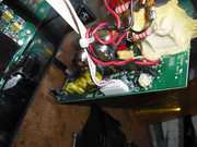 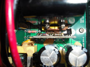 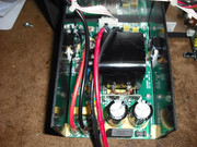 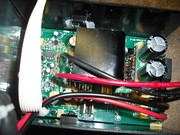 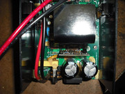 |
|
|
|
Post by mastertech on Oct 21, 2015 9:50:47 GMT -5
Well I have the schematics for the a300 but I think yours might be the SW300. I need more specific pictures like of the back panel of the sub, the fuses that are blowing, an overall shot of all the boards and such.
That brown stuff looks like the regular adhesive used but has been overheated and cracked. But I don't see anything there they may have gotten that hot.
|
|
|
|
Post by thespianator on Oct 21, 2015 14:37:29 GMT -5
|
|
|
|
Post by jeremy on Oct 21, 2015 14:50:51 GMT -5
You know, Jamo's subwoofers never failed at all until Klipsch bought them and started throwing those s**t BASH amplifiers on them... My 2 older Jamo Subwoofers (Jamo C7 SUB, and C8 SUB [larger version the C8 Sub, there are 2]) Are still going strong from when they were bought new. My Jamo C80 SUB (their flagship subwoofer right around Klipsch got them) had power failure when simply being unplugged from the wall.
|
|
|
|
Post by thespianator on Oct 21, 2015 15:47:13 GMT -5
The Klipsch group has also been known for buying up companies and killing off part or all of them, like API (Energy/Mirage +), Mondial (Acurus/Aragon) and probably others as well. Very sad - I really liked the original Acurus amps. New ones are beyond budget.
This plate amp looks pretty cheesy to me. Not surprised it failed, but hoping we can restore it here.
|
|
|
|
Post by mastertech on Oct 21, 2015 22:33:52 GMT -5
Set your DMM to diode scale and test across those 2 AC wires (red and black) lower left of board image.  |
|
|
|
Post by thespianator on Oct 22, 2015 3:04:33 GMT -5
I get 1254. (With no fuse).
|
|
|
|
Post by mastertech on Oct 22, 2015 19:39:29 GMT -5
Well it does not look like there is an early stage short so it is probably farther along and the excessive current draw is probably what is blowing the fuse. Can you get me clearer pictures of these 2 with the wires removed so I can see the components and the traces better? 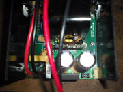 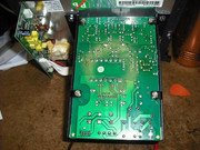 The bottom picture isn't to bad but that reflection hides the traces there. |
|
|
|
Post by thespianator on Oct 24, 2015 13:33:35 GMT -5
|
|
|
|
Post by thespianator on Oct 24, 2015 15:30:27 GMT -5
I have an ESR meter, and now that I've gotten the board off the plate, it's easier to see all the caps. The meter is supposed to work in circuit, but it doesn't always come up with a reading. Some caps do not read values, but if I repeat the test I sometimes get them, and one or two caps - when they actually read - do test high for ESR but due to the intermittent values, I can't be sure if it is correct (one is 7.7 ohms). If you have a schematic I could note which ones. Also - what program do you use to draw lines on a picture? That would be helpful.
|
|
|
|
Post by mastertech on Oct 25, 2015 9:31:02 GMT -5
The picture of the bottom of the board is fine but the picture of the top is not what I need. I need a straight down picture so I can actually see the components and then look at the bottom and see where they go to. I do not have a schematic for this one so we have to do this the old fashion way, lol.
You can use "Paint" to draw on images.
|
|
|
|
Post by thespianator on Oct 28, 2015 12:11:47 GMT -5
|
|
|
|
Post by mastertech on Oct 29, 2015 15:04:12 GMT -5
I did a little investigating on this problem. No schematic was found but this is where I think you should start. I would put DMM on diode scale and do some testing. In the attached pics, the daughter has some diodes and a transistor that I would check and there are 2 transistors on that heat sink that should also be tested. 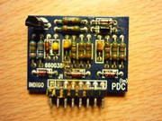 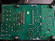 |
|
|
|
Post by thespianator on Oct 29, 2015 17:45:49 GMT -5
Thanks, MT. I would have to remove the daughter to get into it. Same with the two transistors. The cap I pulled had an ESR of 7.7 ohms, btw. Haven't applied power to it yet.
|
|