nashou
Unmoderated Off Topic
Tech in Training.....
Posts: 1,239 
|
Post by nashou on Feb 18, 2016 20:16:16 GMT -5
You have to realize that the audio signal goes through almost every switch on that unit, even if it is selected as "off". So dirty contacts in any of those switches can give a static or distorted signal. Try WD "all" switches and working them in and out and see if anything changes. Yeah I know that. I did do all contacts with the Contact cleaner but not WD-40 . I'll have to take off the from frame to get to them again. the speaker selector switch , power switch and volume control are the only accessible control from the front face plate off. I guess I could try to get it in there from the front, but these switches have slots on the tops which are facing down as it is now in the pic. Its easier to get the cleaner into the switch through those slits than from the from I think. I'll try it like this first then if not go I'll remove frame and work it into the slits. No drying time is needed to test right Mac?  |
|
|
|
Post by mastertech on Feb 18, 2016 20:20:21 GMT -5
Right. No drying time. Just give it a few minutes to drip out the excess.
|
|
nashou
Unmoderated Off Topic
Tech in Training.....
Posts: 1,239 
|
Post by nashou on Feb 18, 2016 20:48:01 GMT -5
Ok Here are the switches.  I propped up the amp on some Marquee shipping foam inserts  so I can spray from underneath and from the front and it can drip onto a towel.  Off to the restaurant to cash out then I'll come back throw the bottom of the amp on and test again. should be in an hour or so. Nashou |
|
nashou
Unmoderated Off Topic
Tech in Training.....
Posts: 1,239 
|
Post by nashou on Feb 18, 2016 23:40:08 GMT -5
Well I worked and worked all those switches and nothing. How ever the Pre out sounds even better. So I guess It has some good effect there.
I think the culprit is the speaker relay. Volume control works really well with the preamp. And I think the relay also send the signal to the head phone out so that is why there is static there too.
I'll investigate the schematics now.
Nashou
|
|
nashou
Unmoderated Off Topic
Tech in Training.....
Posts: 1,239 
|
Post by nashou on Feb 18, 2016 23:55:11 GMT -5
Not sure now, here is the block diagram of the signal path. 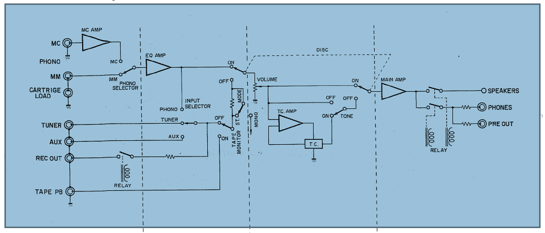 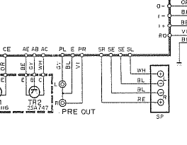 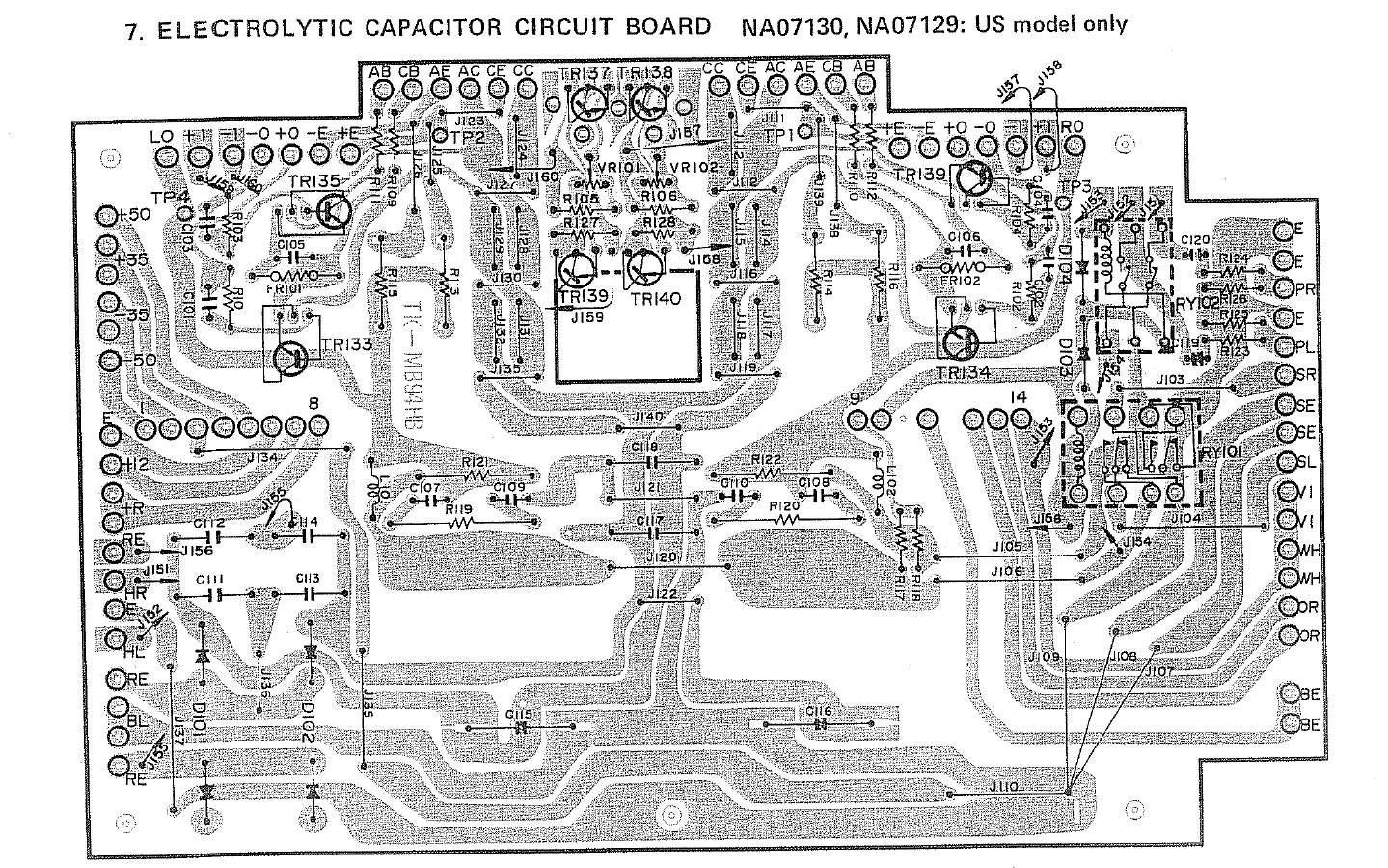 Relay RY101 is a metal box type that has the corners open a little. I tried to spray some cleaner in there and turn the power on and off to work them.  RY102 is a clear sealed type.  Nashou |
|
|
|
Post by mastertech on Feb 19, 2016 11:29:31 GMT -5
If you know which 2 wires are the signal input on that volume control you can swap them and see if the noise stays or moves to narrow down the problem section.
|
|
nashou
Unmoderated Off Topic
Tech in Training.....
Posts: 1,239 
|
Post by nashou on Feb 19, 2016 15:46:40 GMT -5
If you know which 2 wires are the signal input on that volume control you can swap them and see if the noise stays or moves to narrow down the problem section. Well I know there are two RCA Jacks that I think are on the Volume control board. But those might be for the DISC button(Direct coupled) . Looking at the schematic trying to follow the path is dificult. they do have the path for the MM and MC to show the DC path. I'll have to look physically when I get home. Nashou |
|
|
|
Post by mastertech on Feb 19, 2016 16:21:09 GMT -5
Swap the 2 wires shown circled in red or at the other end if easier.  |
|
nashou
Unmoderated Off Topic
Tech in Training.....
Posts: 1,239 
|
Post by nashou on Feb 19, 2016 16:38:21 GMT -5
Ah, you posted while I was looking over the schematics and board layouts getting a head ache !!  Here is the board layout and I think WH and RE are the correct wires.  And the schematics shows a little different?  When I get home I'll look on the Volume board. its easy to get to now that I am open. Nashou |
|
|
|
Post by mastertech on Feb 19, 2016 17:44:06 GMT -5
It is right here. 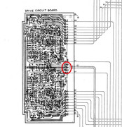 |
|
nashou
Unmoderated Off Topic
Tech in Training.....
Posts: 1,239 
|
Post by nashou on Feb 19, 2016 19:53:36 GMT -5
Ok, Had to remove the bottom to get to the drive board out. I hate those wound around the pin set ups!! Wired frayed after I unwound it to switch over. Oh Well will solder it back on once this is all said and done. White wire end lost about a half inch. Boy is that wire fragile But the distortion stayed on left after the swap. I did not test other output of speaker outs, However I noticed if I touch the wire connected to the left output I get a hum but not if I touch the right wire out. This is right at the pins/wire you see in the pic( thats how the white wire end fell off ). Now that wire set goes to the DISC switch board via a pull out connector.  There are two set of wire that go from the DISC board to the VR board. One is a set of wires in a yellow jacket and the other is a set in a red jacket. 3 wires in each. Also the DISC board is also connected with stiff wire to the VR board. Large pic to see the wires on the left side of the VR board just next to the row of resistors. 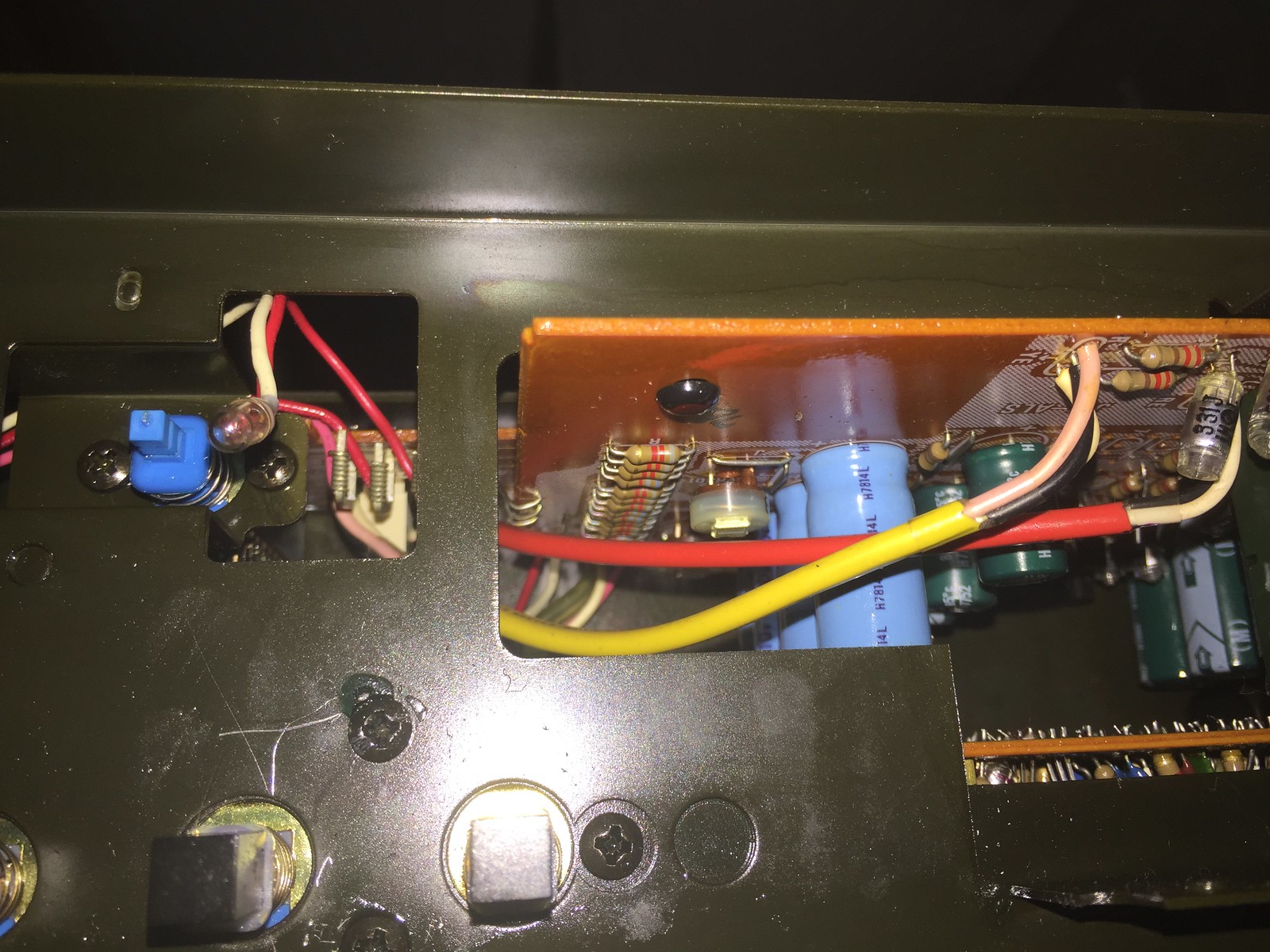 |
|
nashou
Unmoderated Off Topic
Tech in Training.....
Posts: 1,239 
|
Post by nashou on Feb 19, 2016 20:03:28 GMT -5
I also see now that both relays work in conjunction.
Nashou
|
|
|
|
Post by mastertech on Feb 19, 2016 20:10:09 GMT -5
The distortion stayed on the same speaker out. So what does that tell you?
|
|
nashou
Unmoderated Off Topic
Tech in Training.....
Posts: 1,239 
|
Post by nashou on Feb 19, 2016 20:19:47 GMT -5
The distortion stayed on the same speaker out. So what does that tell you? It is not the Volume control.This is where we need to scope with a test tone from the speaker outs back to the volume control out. I did notice two pots on the VR board. Are those before or after the Volume control? Wait I think I have that wrong. So something is wrong in the left channel possibly on the drive board or even one of the transistor outs or the relay. The Input path is ok because the distortion still stayed on the left even tho we sent the right signal through the left input on the drive board. Off to my restaurant to close up be back in a while. Nashou |
|
|
|
Post by mastertech on Feb 19, 2016 20:32:01 GMT -5
Right, not the volume, or any of the switches. Most likely on the drive board or the board they are calling the electrolytic capacitor. Those pots are most likely for idle current or bias adjustment.
I dont know if the scope will even help now. You are most likely going to have to start testing parts with your DMM. If something appears to be testing funny you can compare that reading with the adjoining good channel.
I do not think it is the relay since the speaker and headphone use different contacts. But you can solder a wire across it if you want to make sure.
|
|