nashou
Unmoderated Off Topic
Tech in Training.....
Posts: 1,239 
|
Post by nashou on Feb 24, 2016 11:28:43 GMT -5
Ok I got the resistor parts in and put a 68ohm fusible in series with the 62mA pico fuse and it comes to 75 ohms!!! I didn't notice any resistance on the data sheet would be 7 ohms ! I don't feel like ordering more resters and pay for shipping. So will 75 be too much for that circuit? It looks like its fusible between the two Base's of the main power transistors and between the Emitter of TR 134 and the Emitter or TR 136. Will this affect the audio at at all? EDIT: I also just noticed this may have been worked on before. The left channel looks like it has Radio Shack Resistors put in they have the same bands as the RS ones I have. these are the 330 ohm resters. the originals that were on the right channel have different band colors and its hard to tell as these are dirty or heat stained .  I did buy a better resistor for these , Vishay CMF55330R00FHEK 1% . So we know there was a n issue there. hmmm Athanasios |
|
|
|
Post by mastertech on Feb 24, 2016 12:16:55 GMT -5
That 75 ohm should be fine.
|
|
nashou
Unmoderated Off Topic
Tech in Training.....
Posts: 1,239 
|
Post by nashou on Feb 24, 2016 12:28:01 GMT -5
That 75 ohm should be fine. Ok, For now I just used the 68 fusible alone . I don't have the main output transistors in yet so i'm not too worried for now. I think i'll begin to scope the incoming lines to the Capacitor board. That is +50, E , -0, +0, -E, +E, L0, I+ and I- on the left channel. Would those right channel points still give me good readings with out the main amps in circuit? Nashou |
|
|
|
Post by mastertech on Feb 24, 2016 12:56:49 GMT -5
Give it a try and see what you get.
|
|
nashou
Unmoderated Off Topic
Tech in Training.....
Posts: 1,239 
|
Post by nashou on Feb 24, 2016 13:02:00 GMT -5
Ok, I will. Have some errands to run for work , it will be later today .
Nashou
|
|
nashou
Unmoderated Off Topic
Tech in Training.....
Posts: 1,239 
|
Post by nashou on Feb 24, 2016 19:15:08 GMT -5
Ok did some scope and testing. I first decided to do a voltage readings on the RO and LO RO AC= .019mv DC = 16.7mv LOAC=.069mv DC= 46.7mv !!!! Now on the scoping I had to increase the v/d fro the right channel on some signals. Might be because the output transistors are not in circuit? OPEN BROWSER WINDOW WIDE TO GET PICS TO BE SIDE BY SIDE If you have a big screen 
RO Right channel Scope and LO Left ( Obviously)   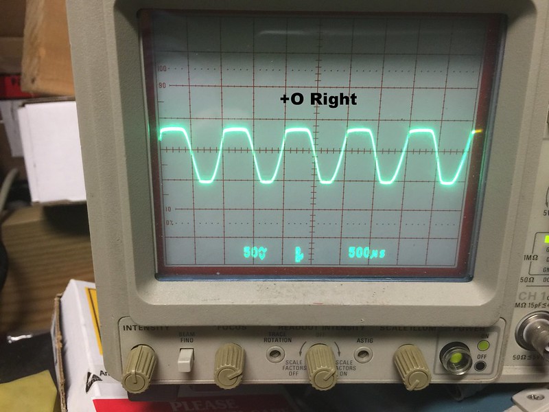  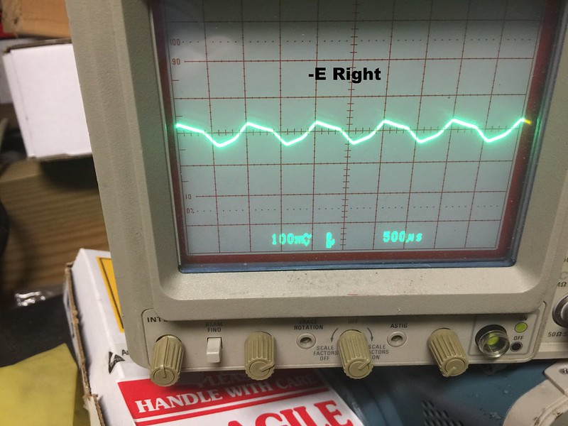 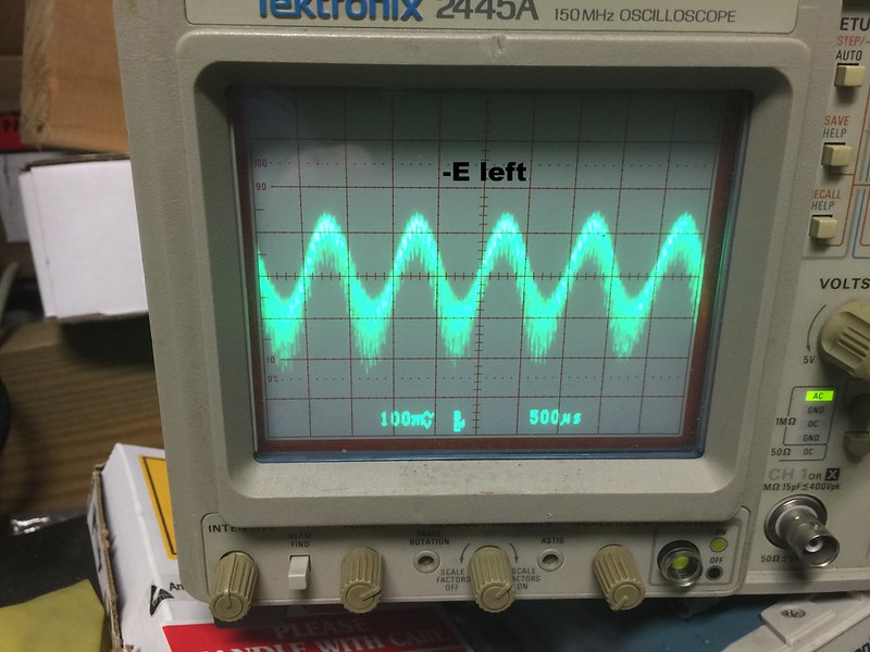   I didn't bother with the other points as they where similar as the ones above. I think I need the new output transistor in there to be sure the right Channel also didn't get screwed up when I shorted TR 134. Athanasios |
|
nashou
Unmoderated Off Topic
Tech in Training.....
Posts: 1,239 
|
Post by nashou on Feb 25, 2016 12:36:36 GMT -5
After reading up on amp distortion I think the problem might be the DC offset. Here is why , on the left channel when I would crank up the volume the speaker protection would kick in for the left only . If i only used the right balance it would not go off at all. This is one sign from my readings that your DC offset might be off. And since it looks like some one was in the left channel before they may have never set it properly. 46mv seems a bit too high. I'll have to do that later today. If that was the reason I'll have to kick myself in the ass for not knowing this before I began all this snooping around and blew the right channel amps. parts from UT source just shipped today. So hopefully they get here next week some time. Just looked at the service manual and the drive board DC offset should be 0-10mv so both are high but the left is way way high.  |
|
nashou
Unmoderated Off Topic
Tech in Training.....
Posts: 1,239 
|
Post by nashou on Mar 7, 2016 19:04:50 GMT -5
Ok I got the new output transistors in, original Sanken. now where were we again?  Ok I pulled the amp block about to get them in. these are the 747's  Nashou |
|
nashou
Unmoderated Off Topic
Tech in Training.....
Posts: 1,239 
|
Post by nashou on Mar 7, 2016 22:50:08 GMT -5
Ok Right channel seems ok after scoping. Now only the left is the one with the noisy wave forms.
I need to look at the drive board left channel parts.
I'll have to remove the drive board while keeping the connectors on and try to scope the
drive board transistors . I'll look over the schematics and try to come up with a game plan.
Athanasios
|
|
nashou
Unmoderated Off Topic
Tech in Training.....
Posts: 1,239 
|
Post by nashou on Mar 10, 2016 19:14:35 GMT -5
Ok so I read up on the distortion issues on the A-1. It seems that the unobtanium 2SK-100 chips sometimes are at fault. So I read on a Japanese blog of one guy swapping around the the 2SK-100's and see if the distortion follows. I pulled the drive board leaving all wires connected and removed the chips from the daughter board and measured them in my tester and then put them in swapped locations. I did notice the problem channel chips pins where they are soldered tot he PCB had some sort or crystallization on them and also part of the pad around the through hole missing. So when I put them back in and desoldered the chips and followed with the 1Khz signal that both channels had a nice clean wave form ! huh so no parts were bad just the chips needed re-soldering. I'll add pics of the test measurements just for thoroughness and since I took them anyhow  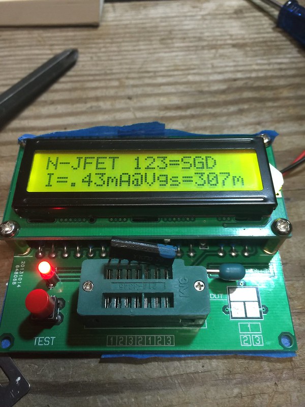   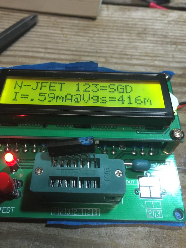   you can see that each chips half are pretty close as intended when they designed them. However the two are not matched to each other. Aslo Mac what do the numbers on the test device mean? I= current right? But the number for the current....how is it arrived at by this device? No instruction came with this. Nashou |
|
nashou
Unmoderated Off Topic
Tech in Training.....
Posts: 1,239 
|
Post by nashou on Mar 10, 2016 19:36:29 GMT -5
Ok the LO and RO look pretty good. but some of the other signals are not. here is a few pics. Left channel still affected. PS also i think using different probes is why the settings are different for the voltage. if I make it the same the one wave form gets really tall. Still a novice with the scope  LO and RO  -E , left is the messed up one. its the same with -/+ O  Nashou |
|
|
|
Post by mastertech on Mar 10, 2016 19:38:46 GMT -5
I would not be concerned about the slight differences in the readings. I do not know for sure what the readings represent but I might assume it might be the current used during the testing process.
But the fact that they appear to be both testing properly I would think they are not a problem.
|
|
|
|
Post by mastertech on Mar 10, 2016 19:43:31 GMT -5
Yes, that second scope image seems to show the distortion if that is the left channel. As I have said originally though, the scope may not help you find the problem part. It can pick up the distortion in so many places that it can be difficult to narrow down. Sometimes just doing resistance measurements with your DMM on components and then comparing readings on same component on good channel can narrow it down quicker.
|
|
nashou
Unmoderated Off Topic
Tech in Training.....
Posts: 1,239 
|
Post by nashou on Mar 10, 2016 19:46:00 GMT -5
Yes, that second scope image seems to show the distortion if that is the left channel. As I have said originally though, the scope may not help you find the problem part. It can pick up the distortion in so many places that it can be difficult to narrow down. Sometimes just doing resistance measurements with your DMM on components and then comparing readings on same component on good channel can narrow it down quicker. yep, thats what I thought . That board is populated with lots of shit man !!! lol Nashou |
|
|
|
Post by mastertech on Mar 10, 2016 19:51:44 GMT -5
Check FR503. might as well check FR501 also.
|
|