Post by gjaky on Mar 14, 2016 13:04:07 GMT -5
I recently bought a NEC XG as a backup for my current XG135LC, and to finish my XG-VNB tests on it. I could buy this machine relatively cheap because it has the dreaded no sync issue, well not exactly, as it syncs but it refuses to recognize input presets.
As this is a common problem I decided to look inside this problem (also now I have more of these problematic NECs than good working), this is not in major focus but for thread starter here are some information about the circuit and the problem.
We have already discussed this in privately with MT, and he is the godfather of these repairs that's for sure, although no ultimate solution has been made yet.
The core of the problem is centered around the NEC system board's PLL circuit. This circuit is present in all PG/XG projectors, and only small changes were made to it.
This PLL cicruit synchronizes the internal waveforms to the input signal. Malfunction of this circuit may appear in scrambled menus, or totally scrambled picture, in light case it randomly refuses to recognize the presets.
The following picture shows the block diagram of this circuit:

And here is the schematic of the XG 1352's system board, which is esentially same as all other XG, and only slightly different from PGs.
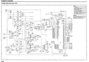
For the PG series the service manual contained instructions on setting this circuit, but performing these settings do not cure the problems on an already problematic board. Interestingly the XG service manuals do not contain instructions anymore, as it say all settings already performed in the factory in case of board replacement.
Unfortunately there is no detailed information about these circuits, but let's see what I could find out so far:
-There are two Voltage Controlled Oscillators (IC8088,D8083,L8081 and IC8089,L8082,D8084) ->their frequency range ratio and range is yet unknown (it can be calculated from datasheets, but would be better to measure a good working board).
-The control voltage (tuning) for the VCO mainly comes from IC8085 a 6bit D/A controlled by the main CPU. To get in lock with the signal a fast frequency variation is also needed that could not be carried out by such D/A. Therfore the secondary (fast) tuning is done with IC8093 FPGA and IC8087B. IC8087B acts as a one opamp PI controller to the FPGA's output, which is a variable width pulse. VR8081 set the threshold level resulting in a "phase-like" adjustment. The output of this opamp is further amplified/buffered then measured by IC8091 8bit A/D. The value this A/D can be monitored in the PG's service menu directly, the service manual says in normal (locked) conditions the voltage at TP8202 should be 2.5V (h80 value, if A/D ref is 5V).
-The VCO output is directly fed to the Xilinx FPGA (IC8093), but since there are voltage level differences a level translator is used to interface the oscillators and the FPGA. Then the FPGA controlls OSD and test signal timing pulses, I believe these timing pulses are the ones which are also stored with the presets and serve as indicators if the there is already a saved preset for the actual input.
Now, as I found with the PG and the XG the problem is the FPGA somehow can't lock the sync with the input signal, this can be caused by a lot of things. To name a few: bad D/A data is loaded acidentally somehow, the fast PI control is either too slow or too fast (or the FPGA's control loop expectation's), the VCOs are detuned (note: we do not know anything about ther relation to eachother), or the worst damaged FPGA program...
And even if it could lock the PLL the before mentioned timing pulses were be different (there were mostly two cases in A/D value) there fore not recognized the input
Next I'll plan to sniff around my good working system board's PLL, especially in regard of the dual VCO's frequency range / ratio
As this is a common problem I decided to look inside this problem (also now I have more of these problematic NECs than good working), this is not in major focus but for thread starter here are some information about the circuit and the problem.
We have already discussed this in privately with MT, and he is the godfather of these repairs that's for sure, although no ultimate solution has been made yet.
The core of the problem is centered around the NEC system board's PLL circuit. This circuit is present in all PG/XG projectors, and only small changes were made to it.
This PLL cicruit synchronizes the internal waveforms to the input signal. Malfunction of this circuit may appear in scrambled menus, or totally scrambled picture, in light case it randomly refuses to recognize the presets.
The following picture shows the block diagram of this circuit:

And here is the schematic of the XG 1352's system board, which is esentially same as all other XG, and only slightly different from PGs.

For the PG series the service manual contained instructions on setting this circuit, but performing these settings do not cure the problems on an already problematic board. Interestingly the XG service manuals do not contain instructions anymore, as it say all settings already performed in the factory in case of board replacement.
Unfortunately there is no detailed information about these circuits, but let's see what I could find out so far:
-There are two Voltage Controlled Oscillators (IC8088,D8083,L8081 and IC8089,L8082,D8084) ->their frequency range ratio and range is yet unknown (it can be calculated from datasheets, but would be better to measure a good working board).
-The control voltage (tuning) for the VCO mainly comes from IC8085 a 6bit D/A controlled by the main CPU. To get in lock with the signal a fast frequency variation is also needed that could not be carried out by such D/A. Therfore the secondary (fast) tuning is done with IC8093 FPGA and IC8087B. IC8087B acts as a one opamp PI controller to the FPGA's output, which is a variable width pulse. VR8081 set the threshold level resulting in a "phase-like" adjustment. The output of this opamp is further amplified/buffered then measured by IC8091 8bit A/D. The value this A/D can be monitored in the PG's service menu directly, the service manual says in normal (locked) conditions the voltage at TP8202 should be 2.5V (h80 value, if A/D ref is 5V).
-The VCO output is directly fed to the Xilinx FPGA (IC8093), but since there are voltage level differences a level translator is used to interface the oscillators and the FPGA. Then the FPGA controlls OSD and test signal timing pulses, I believe these timing pulses are the ones which are also stored with the presets and serve as indicators if the there is already a saved preset for the actual input.
Now, as I found with the PG and the XG the problem is the FPGA somehow can't lock the sync with the input signal, this can be caused by a lot of things. To name a few: bad D/A data is loaded acidentally somehow, the fast PI control is either too slow or too fast (or the FPGA's control loop expectation's), the VCOs are detuned (note: we do not know anything about ther relation to eachother), or the worst damaged FPGA program...
And even if it could lock the PLL the before mentioned timing pulses were be different (there were mostly two cases in A/D value) there fore not recognized the input
Next I'll plan to sniff around my good working system board's PLL, especially in regard of the dual VCO's frequency range / ratio


