|
|
Post by gjaky on Sept 9, 2016 13:40:38 GMT -5
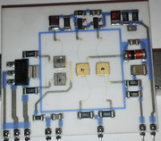
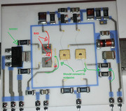
Forum member jenum offered me two 909 neckboards that I couldn't resist to buy, one of them was known defective (but not he hybrid), so I decided to sacrifice it on the altar of science... For the sake of completeness, here is how the Barco hybrid looks in its original form:  And this is after removing the RF shield box:  The first picture is from a newer neckboard, the second is an older one, note that they changed the peaking on the newer hybrids (2x75Ohm vs 2x220 Ohm and 1.2k vs. 330 Ohm). Also interesting to see how long bonding wire they used for connecting to the transistors, I would think this long wires are adding a lot of (unwanted) inductance EDIT 2020.05.07: but it is eliminating a lot of parasitic capacitance because the grounded heatsink tab is just underneath that area. This is how the schematic diagram looks like of the hybrid, for reference there is the schematic of the Sanyo VPA hybrid.  There are further close-ups from the output transistors: Q1:  Q2, please note the high frequency power transistors are often constructed of several "smaller" transistors tied in parallel, with an internal fuse, a part of these small transistors might burn out in an event of failure, still the overal transistor might remain functional, the grey parts circled, those parts are probably burnt out already, since this transistor still measures good from the outside.  Q3, was somewhat damaged when I ripped-off the RF shielding, still the transistor is functional.  Q4:  |
|
|
|
Post by mastertech on Sept 9, 2016 18:42:23 GMT -5
So what have you concluded in the name of science, lol.  |
|
|
|
Post by gjaky on Sept 10, 2016 1:31:25 GMT -5
So what have you concluded in the name of science, lol.  I think they did not care much about this circuit or did not have proper high-frequency knowledge... When dealing high frequency symmetry is usualy a good aid, here there are several paralleled components that sees different stray inductances, so they might not even that parallel anymore from high frequency standpoint.  Also they paralleled Q3 and Q4 probably to fit in the transistors dissipation limit, but both transistor have to stand the whole voltage (and in this circuit Q3 and Q4 is under the most stress both in dissipation and in voltage) once they took the pain to use two transistors for that stage they would be better to go with a so-called sliding cascode circuit, where two lower voltage transistor could be connected in series and adding the two base resistors would ensure equal voltage division between the two transistor. And as you know with going down with transistor breakdown voltage the frequency go up... EDIT 2020.05.07: With the two transistors parallel they have double load capacitance as well and in these kind of circuits load capacitance that eats the bandwidth the most.
 |
|
|
|
Post by Casethecorvetteman on Sept 14, 2016 1:34:27 GMT -5
So can you make it far better and more reliable?
|
|
|
|
Post by gjaky on Sept 14, 2016 11:19:11 GMT -5
So can you make it far better and more reliable? No, I don't think so. With home tools it is basically impossible to fiddle around the RF shield box. I just pointed out how I'd have done that. BTW is there a known reliability issue with them? |
|
|
|
Post by Casethecorvetteman on Sept 15, 2016 0:45:36 GMT -5
Not that i know of.
|
|
|
|
Post by radiohead314 on Sept 16, 2016 7:56:04 GMT -5
He my girlfriend says perhaps the big leads are because of the cooling area needed.
|
|
|
|
Post by gjaky on Sept 16, 2016 13:39:18 GMT -5
He my girlfriend says perhaps the big leads are because of the cooling area needed. For what?  |
|