|
|
Post by Casethecorvetteman on Sept 30, 2016 6:58:39 GMT -5
Well that sounds to me like you may have to send that MOOME card back for replacement.
|
|
tums
New Member

Posts: 10 
|
Post by tums on Oct 1, 2016 16:08:33 GMT -5
That's not the answer I was hoping for. Because of the reply of Moome I would like to measure the internal videosignal of the Barco. But, like I mentioned before, all the documentation I find is for the 1209s. The videochain of a 1209s is different from my 1209/2. Is there anyone who knows where to hook up my scoop? After all the answers I think it's the last thing to check before I send it back.
|
|
|
|
Post by mastertech on Oct 1, 2016 18:23:20 GMT -5
What is the board number that the moome board plugs into and what port is it?
|
|
|
|
Post by Casethecorvetteman on Oct 2, 2016 4:25:21 GMT -5
What is the board number that the moome board plugs into and what port is it? It goes into the socket Port 3 would normally occupy. It should work on any Barco with a Port 3 slot, because apparently all Port 3 Barco cards are the same part. |
|
|
|
Post by Casethecorvetteman on Oct 2, 2016 4:27:57 GMT -5
That's not the answer I was hoping for. Because of the reply of Moome I would like to measure the internal videosignal of the Barco. But, like I mentioned before, all the documentation I find is for the 1209s. The videochain of a 1209s is different from my 1209/2. Is there anyone who knows where to hook up my scoop? After all the answers I think it's the last thing to check before I send it back. Mate if youre not able to perform the tests then its time to ship MOOME the card for him to test and/or replace. It works perfectly fine with the Port 3 card, so id be reluctant to believe the set is at fault here. |
|
|
|
Post by gregstv on Oct 2, 2016 18:01:25 GMT -5
check the signal level on the cable between the MOOME and the switcher.(the board the MOOME plugs into with the white cable. There is only RGB and ground on this cable so it should be easy to measure. If your in doubt of the readings, fit the port 3 card and measure off the same point for comparison. The output level on both cards should be very simular. Use a test pattern to make measuring easier.
|
|
tums
New Member

Posts: 10 
|
Post by tums on Oct 2, 2016 19:09:50 GMT -5
Thanks everyone.
This week I'm away from home, I'll test it when I'm back.
So be patient and I'll tell the results here.
|
|
tums
New Member

Posts: 10 
|
Post by tums on Nov 3, 2016 15:31:39 GMT -5
Okay, here we go. I placed the original card back and selected 1680x1050, because this gives me a good picture. Well, it gave me a good picture, I've set all the settings in the middle position. But that's the least of my problems. I connected my scope to the green RGB signal on the yellow cables between the port 3 board and the RGB decoder, put the zero line one square beneath the middle line. 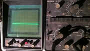 Mabey it's not the right way, but I put de scope in AC mode to get a complete picture on the screen. My knowledge of videosignals is limited, but I think I can make a point. 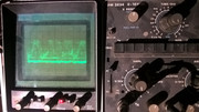 To have a nice steady picture I selected a 100 IRE picture. This gave me the following screen: 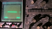 You can see that the voltage difference of the signal is about 0,7V. So now the same trick with the moome card inside. To see the whole signal, I had to adjust the zero line. 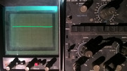 On the next picture you can see that the difference is now about 1,3V. 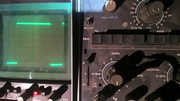 By adjusting the gamma from maximum to minimum I could bring the signal down to 1,0V. 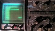 Then I was curious what would happen when I put the scope in DC with the zero line on the bottom line of the bottom square.  You can see, the signal is lifted to 0,05V and has a maximum of 1,0V. So, that would explaine the question of moome about the 0.7V to 1.0V. For a good picture I need a 0.7V signal and the moome card gives out a 1.0V signal. Back to emailing Moome for a solution. |
|