Post by mikeb on Feb 5, 2017 15:46:27 GMT -5
Some history on this unit to get started: I acquired this receiver from my older brother, reason being it wouldn't power on for him. His baby girl pressed the power button many times instantaneously, resulting in it not powering up. So he gave it to me, where if I could find and repair the issue, its mine. I have some experience with troubleshooting automotive electronics, aka sensors, but limited with circuitry troubleshooting. I have soldered electrical components before, I like to tinker with stuff in the garage a lot, but I haven't ever had to deal with such fine components.
I plugged the unit in recently and nothing happened when the power button was pressed, no relays engaging or anything, so I started google searching, stumbled across this forum, and found that if you hold the straight and tone control buttons, press and hold the power button, you can enter a self diagnostic mode to help with troubleshooting. I did this and came up with DC PRT: 000L. When I went to menu 8 on the diagnostic, the PS value was within range, and the DC value was at 000. Absolute zero.
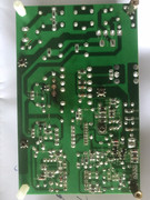
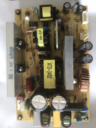
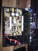
I continued on to removing the case of the unit, inspecting the circuit boards for anything that may look like it was fried and everything appeared to be okay. I searched for info on this unit that could pertain to power troubles, didn't find specifics for this model, but a few earlier models appear to have many of the same boards and components. The first component checked was the transformer on the primary coil side, which checked out to have adequate resistance. I read somewhere about voltage checks on Operation Board 2 at CB134: pins +12A, -12A, using AGND for the negative probe.
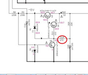
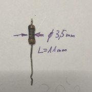
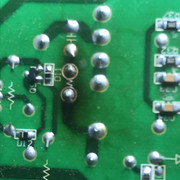
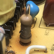
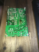
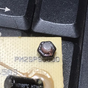
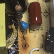
I couldn't get the probes into the connection due to the tight spaces on the plastic retainer clip with the board installed in the unit. I removed the retainer clip on the back, which exposed the ends of the wires, so now I'd be able to test these voltages when power is applied to the unit. Upon powering up, I had a component burn out in front of me. It ended up being R11 on Main Board 1. This could have been due to me removing the retainer clip on CB134, which ended up emitting a small spark when I reinstalled it. I did not realize that the wires would float within that connection when the clip was removed. So as far as I know, I have a burned up resistor, all other components look fine still, but there is no telling until the board is completely removed.
Any helpful input to resolving this issue will be greatly valued. I don't need any critics to tell me to take it to a repair shop though. I got this unit in non-working condition, so I'm no too upset if I can't get it to work. Id rather buy a new working one than spend the money for someone else to repair this. I have also located the service manual for this receiver, so any references for specific circuits are more than welcomed in troubleshooting the issue. My time is limited at home, so as I get time, I will report back to this thread, feel free to load it up with content to get me started.
Thanks all,
Mike B


