|
|
Post by zaibatsu on Feb 17, 2017 0:47:08 GMT -5
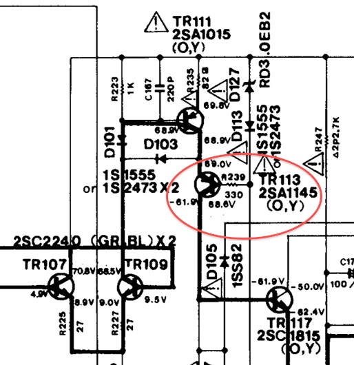
Hi, posting here under suggestion of Nashou (from AK). Amp is a Yamaha A-700 integrated from 1983-85. Schematic here or hifi-engine manual page here.
I have been advised the schematic voltages are incorrect, so I've just been comparing to the good channel for now.
I blew a channel on this a while ago (relay stopped closing - still does not close).
I know my diagnosis method thus far has been less than perfect, but I've tried to provide as much info as possible below.Failed parts were as follows: - TR139/TR141 (outputs)
- TR135/TR137 (drivers)
- TR135/TR137 (predrivers)
- TR113/TR115 (predrivers?) from memory
- TR125 (bias transistor) from memory
- R111, R113, R301 (fusistors)
I replaced everything that I tested as dead, but I was still getting strange voltages on the bad channel transistors (with TR-A113 getting very hot), so I ended up replacing all semiconductors on that channel. The bad voltages haven't changed (so I don't think I made any mistakes / made anything worse) but the problem isn't fixed either. In full, the work done on the amp so far: - Recapped (all electrolytics on both channels, but no other types)
- All bipolar transistors replaced on bad (left) channel
- All zener diodes and diodes replaced on left channel
- 2x FETs on bad channel tested with transistor tester: OK
- Bias transistors replaced and tested
- Checked for solder bridges and short circuits, retouched most if not all solder joints
Other info: - I currently have the amp set up on DBT with 470Ω resistors across the B/E pads for all output transistors
- Drivers transistors are in place
- The bad voltages trace back through both the drivers and predrivers and I have tried replacing the predrivers a few times. A113 is overheating even on the DBT.
- All parts / semiconductors were purchased from mouser so no concerns about counterfeit parts
- I have compared in-circuit resistance of most resistors (with the good channel) and can't find any failed ones. I suppose the next step is to start pulling those and testing out of circuit, perhaps starting with all the fusible ones?
- I haven't tested any non-electrolytic capacitors. Are there any of these that I should test? Possibly the bright green ones across fusistors?
- I haven't tested anything outside of the main amplifier board, could the problem be elsewhere by any chance?
Other things I've tried:
- Lift R213 => DC Servo disabled (via IC104)
- Lift D147 => Class A disabled (via IC105)
- Join Base legs of TR127 / TR129 => Bias generator disabled
None of these fixed the problem, if that helps eliminate some areas? Some measured voltages below: 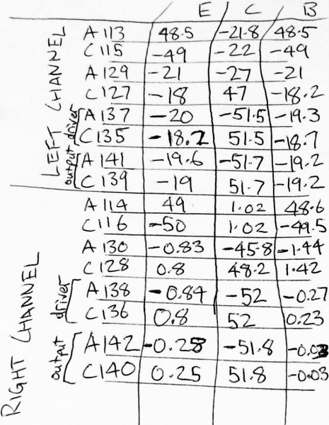
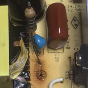
Overheating transistor:
Appreciate any help!
|
|
|
|
Post by mastertech on Feb 17, 2017 17:05:27 GMT -5
What does the unit actually do when you turn it on?
I only see a relay on the left channel. Is this correct?
Does either channel work correctly?
|
|
|
|
Post by zaibatsu on Feb 17, 2017 20:25:16 GMT -5
What does the unit actually do when you turn it on? I only see a relay on the left channel. Is this correct? Does either channel work correctly? Hi thanks for the reply! - The lights turn on normally when powered up. - There is a single protection relay for both channels, so it doesn't engage (I would imagine because of large DC offset on the bad channel due to the bad voltages). The relay only engages if both channels are good. - I don't actually know for sure that the right channel is good either, but the voltages seem more normal on that one? It didn't blow output devices, that's all I know. If it helps at all, I have an identical working amp that I've repaired a blown channel on before, and the relay will click with the 470Ω resistors in place of the outputs (while on the DBT) when all is well - so that much I know is OK. I can also take static measurements from it if needed, but I'm a bit reluctant to take live ones (it's used daily and I don't trust myself to not slip with the probe). |
|
|
|
Post by mastertech on Feb 18, 2017 10:06:22 GMT -5
I was looking over some of the voltages you posted and it seems to be all over the place. Give me some time to go over the schematics and see if I can come up with something.
|
|
nashou
Unmoderated Off Topic
Tech in Training.....
Posts: 1,239 
|
Post by nashou on Feb 18, 2017 22:06:34 GMT -5
Welcome Ziabatsu !! Your in good hands with Mac.
What you can do to help prevent slippage with the probes is cover up most of the probe with tape or that liquid rubber and only leave the very tip exposed.
Nashou
|
|
|
|
Post by zaibatsu on Feb 21, 2017 1:11:12 GMT -5
Thanks to both of you.
I'll be waiting patiently for suggestions.
|
|
|
|
Post by mastertech on Feb 21, 2017 9:34:42 GMT -5
Well I spent some time going over the schematics and looking over the voltages you posted. It looks like you have a problem with both channels. I was also taking into account all the parts you said you have already changed. After all this I really do not have any suggestions. These circuits are difficult to troubleshoot as Nash and I found out previously. You almost have to remove and test every component to find the problem. I don't even have any thoughts as to where to start. These circuits are not like newer amps and receivers that you can pinpoint better. If 1 part is bad is throws off voltages everywhere. Of even with just a bad connection. So I hope you can find the problem but I am sure it will take some effort. Sorry.
|
|
nashou
Unmoderated Off Topic
Tech in Training.....
Posts: 1,239 
|
Post by nashou on Feb 21, 2017 13:26:34 GMT -5
Id look at all resistors out of circuit and then move to all caps that you have not replaced . That is a complicated circuit after looking at the schematic . Then you would have to look at all power sources to make sure they are correct . If there is way to disconnect the main amp board from the Power supply and measure that this main voltages are ok . Did you check the voltages at TR 147- TR 152?  If you look you can see that the +/- B line comes in first at TR 135/139 +, and TR 137, TR 141 - . They are about 20 volts lower than should be. Might be something pulling it down. Here is where you have to start pulling parts to see if that voltage comes up . Not sure where to start tho , this is where you have to see where that line goes and maybe start from the furthest transistor or if there is a resistor before it that might cut off a series of TR's. Like R135. Not sure if this is the way to go as I myself am learning the trouble shooting aspect of reading schematics. Also pulling TR's will be needed Like TR146 is on that line . If we start getting some where maybe Mac might have an Ah Ha !!!! moment and jump in. Nashou |
|
|
|
Post by zaibatsu on Feb 21, 2017 15:01:31 GMT -5
Thanks anyway, I'll keep trying to find something.
So far all I have is TR113 getting super hot. I've left its legs long so it doesn't burn up.
1.
I haven't checked TR147 - TR152 voltages, should I compose a list for those? Would B/E be enough for you or is C needed as well? I just find the collector the hardest to measure without shorting things, but I'll wrap up the leads anyway.
2.
I just checked the voltages going into the board at the blue/red wires on the L/R channel.
Both seem to match with +/- 50.75V. I think that's good. Are there any other points I should check power?
3.
I had another idea - do you think it's worth chocking the relay closed and measuring DC offset at the speaker terminals to see if the "good" channel is ~zero or not? Is it possible to check DC offset without outputs in place? I feel like it'd be useful to know for sure if one channel is okay.
4.
Do you guys think having an oscilloscope might help narrow this down? I watched a few youtube videos on connecting a tone generator to the input and then checking the output at various stages to try and narrow down where the signal stops showing. Would something about this amp design stop that being useful, or would that work (and can it be done while on DBT)? I could try and borrow one if it's useful (even for the sake of learning).
I'll get those voltages first and then think about what to pull. Are there any rules of thumb on what can be pulled without causing other things to blow up?
|
|
nashou
Unmoderated Off Topic
Tech in Training.....
Posts: 1,239 
|
Post by nashou on Feb 21, 2017 22:06:32 GMT -5
The B voltage lines should be 71 volts +/- or plus or minus a couple volts. 51 volts is not good. Something is bogging those lines down . I had the same issue on my EQ board on my A960 amp. If you could disconnect those two lines and measure the voltage off the rectifier or off the main filter caps . Because the voltage at the collector TR 135,139( positive line) and at the collectors of TR 137 and 141 ( negative line) should be close to 72 volts, not 51 . So we have to see if the main power is ok with no amp board connected. Just the power supply board independent . Im just guessing here but I always have thought first make sure the power supplies are working as they should with no load. Remember I am learning as well here.  Just a thought, the replacement TR's you got. Did they have the same pin out designations for BCE ? Some look like the same parameters but the legs are different . Nashou |
|
|
|
Post by zaibatsu on Feb 22, 2017 3:32:55 GMT -5
Hey Nashou - Are you sure? This is measured while on DBT, would that not change the voltages? And are you taking into account that the schematic voltages are supposedly incorrect too? I can probably carefully double check this by putting my good amp on the DBT taking the same measurement (if you think 51 is wrong). Would that suffice? Totally agreed on making sure the power supply is all good first. Transistors are all from avionic's recommendation so I don't think there are any incorrect pinouts (and I've used a number of them to successfully fix other amps) - but there are definitely a handful of the smaller early-stage ones that I haven't used before / checked. So I'll do that. Edit:Been poking around with meter when bored, power off, found an anomaly in B-E resistance TR118 (right ch) is the equivalent of TR117 on the left ch. TR117 7.28 MΩ (bad channel) TR118 1.58 MΩ ("good" channel) TR117 0.87 MΩ (good amp) TR118 0.90 MΩ (good amp) Does that give you any clues?  Edit 2: Edit 2:
I took some more static B-E resistance measurements, clearly there's 3 transistors that aren't matching the "good" channel, the others all seem to match I feel like there may be component/s parallel with those transistors' B-E legs that are bad (TR113, TR115, TR117). The even numbers are the corresponding "good" channel transistors.  I might take the same static measurements from the working amp to check, but I suspect not having the outputs in place will cause a global anomaly. I might temporarily put the new outputs into the dead amp so that I can make valid comparisons, presumably the DBT should protect those guys anyway even if I turn it on. |
|
|
|
Post by zaibatsu on Feb 25, 2017 2:49:33 GMT -5
While chasing components connected to TR117 (due to the above anomaly), I noticed D153 (screenprinted on board) is D125 in the service manual drawing. D153 is a Zener, D125 is a Diode. Trying the swap now! Edit -Relay click! Wooohoooo  Will let the excitement die down before I start putting the new main output transistors in. Edit 2 -New outputs in and relay still clicks successfully on DBT. I need to clean some things up before I take it off the DBT and set bias. Will update. Edit 3 -
Took it off the bulb tester, plugged into mains. Relay still clicks! - Checked DC offset at speaker terminals, OK (-0.1mV left / 0.3mV right ). - Set the bias roughly for now (~15mV), seems to be biasing OK. - Checked Class-A mode, gets nice and toasty. Wasn't game to leave it on too long - Still need to set the Class-A switching point (bit of an ordeal with dummy loads and tone generator, will do it tomorrow) Once the last step is done I'll re-check the bias and try it with some speakers! So far things are looking good. |
|
|
|
Post by mastertech on Feb 25, 2017 11:42:54 GMT -5
Let us know if it works.
|
|
nashou
Unmoderated Off Topic
Tech in Training.....
Posts: 1,239 
|
Post by nashou on Feb 25, 2017 16:00:30 GMT -5
Sweet !!!, yeah Yamaha is notorious for improper Schematics or Screen printing on boards. Its trying to figure out which is the correct one that drives you nuts or cost you more money in parts blown !!!
Nashou
|
|
|
|
Post by zaibatsu on Feb 27, 2017 3:39:10 GMT -5
All works!  Thanks for the support! New output transistors w/ fresh thermal paste:  Setting Class A switching point with dummy loads:  Back in black!  |
|


