|
|
Post by zaibatsu on Feb 28, 2017 9:05:29 GMT -5
nashou I think I spoke too soon!  The bias behaviour on the bad channel is not matching the good one. It's playing fine (listening right now) but while the right channel bias is behaving exactly like my good amp, the left channel AB bias needs to be set at 1/3 of the right channel for them to stabilise equally in Class A. I pulled and tested 0.22Ω emitters on that side (OK), and also checked TR127 / TR129 (OK) which I think are responsible for bias. I pulled and resoldered the bias trimmer as well (vishay multiturn) and I don't think there's any problem there. I wonder if component subs would be responsible? But the outputs / drivers / TR128 / TR130 / TR125 (bias transistor) on the good channel are the same parts as the bad one, so none of those should be to blame. I'll look into the remainder.
|
|
|
|
Post by zaibatsu on Feb 28, 2017 9:43:39 GMT -5
To add more info: The thermal compensation circuit *does* seem to be working, it just seems like the A-bias increase happens faster / has a larger multiplier on the bad channel. Correct behaviour in Class A is that bias slowly rises across the emitters to ~170mV and then as the heatsinks get hot, that drops to 115-120mV and stabilises there. This does happen on both channels OK, but if you set the AB bias at 15mV (factory), when switched to A the bad channel bias rises faster and stabilises at a higher value. I've left it at 5mV for now. Edit -Just checked my subs vs. still-working originals and noted the large variation cases: TR123, TR143 original = 2SC2603 (hFE = 429); Sub = 2SC945C (hFE = 170)TR121 original = 2SA970 (hFE = 232); Sub = KSA992F (hFE = 435)I feel like (from schematic): - TR143 has something to do with the bias current to the L output pair (like TR144 for R output pair) - TR121 and TR123 have something to do with the L bias transistor's impact on the L output pair (i.e. thermal compensation) - TR145 I'm not sure what it's responsible for, and I can't see its equivalent on the R channel, but this was a victim of my blind replacement (and connected to the Auto Class A IC105) so I'm tempted to restore this one too (hFE = 429, original was either 235) I'm going to revert all these guys and see what happens!  |
|
|
|
Post by zaibatsu on Mar 1, 2017 0:35:47 GMT -5
Edit -Fixed it. Will update this post after proper testing. I ended up trying numerous things that didn't fix the problem (in an attempt to fix it), but I think they were positive changes since they would have made the L/R channel behaviour more consistent anyway: - Replaced 0.22Ω emitter resistors with new vishay items
- Replaced Class-A transistors (above post) on bad channel with the original (working) items, to match other channel
- Replaced bias-circuit differential pair on both channels with hFE-matched pairs
- Replaced input differential pair on both channels with hFE-matched, higher gain pairs (still within SM hFE spec. range)
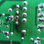
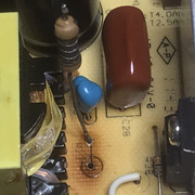
None of these things seemed to fix the problem (L bias ending up ~30mV higher than the right in Class-A), but there was one thing I hadn't tried (that I meant to and forgot about). TR127 (from the TR127 / TR129 pair, which connect to the bias transistor) had a slightly lifted PCB track on collector. I didn't see the need to rewire it since it passed continuity testing from the meter, however I did wonder since these transistors get fairly warm, if there was a thermally influenced loose connection there.
I hard-wired that track, and the bias seems to be tracking consistently between the L/R channels (+/- 5mV in Class-A).
I think this was the problem.
Will give it a few hours of loaded testing soon.
Edit 2 -
Still testing, but with L/R bias set at 15/15mV in Class AB, the values seem to stabilise at 120/125mV in Class A.
Much better! Will keep testing.
Edit 3 -
Fixed, been playing in Class A for a few hours and L/R bias is nice and stable.
|
|


