|
|
Post by robin36mac on Apr 13, 2019 14:05:13 GMT -5
Hello all, I have a new incomer at home... I've been able to get a second 909 Split-pack set ! I may use it in a blend in future, if I can get a room good enough, anyway, for now it will be a great test chassis. It's coming from the very same installation as my first one. It's working almost fine, but one of the video amp is not going great.  So you can see : I have spare, but I would be happy to save one and see if we can save this one. Hoping it may be something else than the hybrid. Being a test chassis, on floor, doing some measurements are easy. They are the later R7630275, with ABL connector. It had the ABL option like my other set, I removed this even before starting the set, lesson learned from the issue I had beacause of it... I confirm that if I swap the video amps, the issue follows the video amp, confirming the issue is there. I first checked G2 voltage (from feedback on J100), the signal is coherent with the neighbor video amp, seems normal. I then checked the video signal on M1 and M4 test points : The signal is correct on hybrid emittor (M1), but shows the issue on the output going the the cathode (M4). M4 is upper trace ; M1 is the lower trace.  Then let's see the 190V supply line and...  There is something here. So I checked around Q8 : - On the collector (210V supply from frame) : I measure 230V, quite stable - On the base and on emittor, the same trace as just before. So something is going wrong on the 190V regulation. But it's a loopback regulation, so I really wonder how to proceed to investigate that. Is opening the loop an option ? Any suggestion are welcome, I can post scope trace, measurements as needed ! Robin |
|
|
|
Post by robin36mac on Apr 13, 2019 14:32:28 GMT -5
I just checked also around Q103 :
Check with multimeter there is 3mv DC + 8mV AC on the resistor network R119/120/121
Not enough to trigger it (as current limitation ?).
|
|
|
|
Post by hulio on Apr 14, 2019 3:17:57 GMT -5
Nice work, Robin.
I guess, if safety resistor SR1 would be bad, you won't get any picture out of the red tube. How about D108 and C106 ? Test them too.
Also, to exclude the 190V regulation as the culprit, swap the output driver only (R7630275S).
|
|
|
|
Post by robin36mac on Apr 14, 2019 13:38:56 GMT -5
Hello Hulio,
Good idea to swap sub-board !
Result : It's the sub-board that is faulty.
Good news is the hybrid is out of the equation.
SR1 is OK
D108 is OK (0,57V in forward, not passing in opposite way)
C106 is OK (106nF)
Robin
|
|
|
|
Post by robin36mac on Apr 14, 2019 14:02:01 GMT -5
Measured, onboard (I know it's not fully fine to test in circuit, but it's SMD and access is quite epic enough...)
R122, R123, R124, R125, R126, R127, R128, R139 are fine
P100 is set at 250 Ohms
Measuring 1,5nF for C107 (being onboard, the measurement can be off)
|
|
|
|
Post by robin36mac on Apr 14, 2019 14:29:45 GMT -5
SR2 is fine ; I'll check tomorrow if the -9VA and -5V lines are fine
|
|
|
|
Post by gjaky on Apr 15, 2019 2:17:50 GMT -5
I just checked also around Q103 : Check with multimeter there is 3mv DC + 8mV AC on the resistor network R119/120/121 Not enough to trigger it (as current limitation ?). I would not trust DMM measurement on that, only for resistance measurement... Make sure the resistance of the network is 0R33. Q103 is not a HV transistor and there is no clamping on its Base or C-E terminals, so it might get zapped at some point (leakage?) This regulator uses the -5V as the reference, so any instability translates to voltage ripple on the output. Also it would be possible to open up the feedback loop: cut the trace between I102 pin1 and Q104 base. I am too lazy to further analyze the circuit, but you should apply a DC voltage to Q104's base between -5->+12V eg. with a potentiometer (just like the opamp's output would do). By the feel: when the voltage at Q104 is low the output should be low on the output too.
But if you chose this way check twice before frying the hybrid  |
|
|
|
Post by robin36mac on Apr 15, 2019 14:31:50 GMT -5
I just checked also around Q103 : Check with multimeter there is 3mv DC + 8mV AC on the resistor network R119/120/121 Not enough to trigger it (as current limitation ?). I would not trust DMM measurement on that, only for resistance measurement... Make sure the resistance of the network is 0R33. [...] For this DMM measurement, I used a True RMS (Fluke 189), usually, it is reliable for this kind of check, the frequency here being reasonnable. Such resistance is difficult to measure because of contact resistance... But should not be far. I got the idea to run the sub-board alone (it would be very convenient, leaving the hybride alone); but Q8 being on the other board, a attached a BUX86 monted on a connector, going on J104. Unfortunately, this is no help, the line is not loaded so the regulation just output some spikes, it don't behave the same. Let's forget. Going back to the supply voltages : 12V :  -5V : Some spikes, but at a quite different frequency (see time scale)  -9V : A little off, but is unregulated  But I don't see the pattern of the 190V line. Which still behave the same. And now I got a new issue  The video signal is VERY noisy. 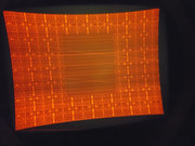 That's not the video amp itself, that's not the RGB driver board... (swapped all that) I'll check video cables... To be continued... |
|
|
|
Post by robin36mac on Apr 15, 2019 14:42:09 GMT -5
And now I got a new issue  The video signal is VERY noisy.  To be continued... Un-twisted and played with the video cable and that noise issue has gone. I have a spare one, I will put it after the video amp issue is solved (no need to damage another one). |
|
|
|
Post by gjaky on Apr 15, 2019 14:50:25 GMT -5
You can load the circuit very well with 2kOhm, but be prepared to dissipate ~20W -> a 25W 230V incadescent bulb would do for example.
From the picture it looks like mostly the blanking is gone (G2?)
I have two 909 neckboards here (without a matching projector) one have a burnt out component somewhere, I have to check if it is on the main board or the sub board, if the sub board looks intact you can have it for the cost of shipping (from hungary.
|
|
|
|
Post by robin36mac on Apr 16, 2019 2:34:10 GMT -5
You can load the circuit very well with 2kOhm, but be prepared to dissipate ~20W -> a 25W 230V incadescent bulb would do for example. Good idea. The ballast transistor will require heatsink also. Looking at it, I missed on the socket schematic the 10µF capacitor (C7) (I didn't get there wasn't), surely that's needed. I have two 909 neckboards here (without a matching projector) one have a burnt out component somewhere, I have to check if it is on the main board or the sub board, if the sub board looks intact you can have it for the cost of shipping (from hungary. Oh, that's a nice offer !! Robin |
|
|
|
Post by gjaky on Apr 16, 2019 15:49:01 GMT -5
I have two 909 neckboards here (without a matching projector) one have a burnt out component somewhere, I have to check if it is on the main board or the sub board, if the sub board looks intact you can have it for the cost of shipping (from hungary. Oh, that's a nice offer !! Robin So I've checked my stash, and sadly it is the subboard that has the burnt out component, moreover I forgot that I started to cannibalize the board already, two burns trimpots are missing... |
|
|
|
Post by robin36mac on Jun 3, 2019 10:10:42 GMT -5
Hello,
Just a word to let you know, that I'm not giving up at all ; I'm just quite busy these days on others project (car painting, ...)
Just on hold for some time ;-)
Robin
|
|
|
|
Post by mastertech on Jun 6, 2019 11:26:12 GMT -5
What kind of car?
|
|
|
|
Post by robin36mac on Jun 6, 2019 13:18:44 GMT -5
I did that rear fender on a Peugeot 307 hardtop convertible for a friend (metallic & pearl) :  But I have a lot of dust on the clear coat. That's still better that what I've done already for now. I'm improving my process to solve that (cover the floor, ventilate with filtered air ; and put a special glue-paint on the wall that will catch the dust), I'm practising on an red Alfa 156, that I got for very cheap. My main car is a 2002 Camaro (Hello to Case The Corvette !) |
|


