Post by tjmotter on May 8, 2019 15:18:54 GMT -5
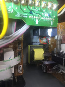
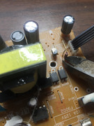
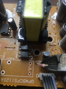
Most people don't realize this but pressing the power button on an Onkyo receiver does NOT turn off the power. The power button merely sends a signal to the MAIN CPU telling it to close a relay (to turn the system on) or open a relay (to turn it off). When you press the power button on an Onkyo and nothing happens (no clicks, no brief lighting up of the front panel) the root cause is often a blown coil in the main power relay. This tutorial will guide you through how to replace this coil and ensure that the fault does not re-emerge.
Here is what you will need:
1) a medium star (philips) screwdriver
2) a small set of pliers and a pair of wirecutters
3) a soldering iron
4) some solder wick (easiest way to remove the solder from the 4 post relay and the 2 post resistor) - www.mouser.com/ProductDetail/MG-Chemicals/424?qs=sGAEpiMZZMuzEnlwMwYUNk0EBT49tEUvIIid%2F1ys6zM%3D
5) some solder
6) an exacto knife
7) 1 relay - www.mouser.com/ProductDetail/te-connectivity/8-1419125-9/?qs=0cdP5f6kAtEd%2FNehBp48tA%3D%3D&countrycode=US¤cycode=USD
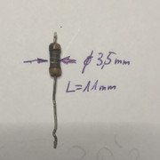
8) 1 high precision 150ohm 1/2 watt resistor - www.mouser.com/ProductDetail/KOA-Speer/MF1-2DCT52R1500F?qs=%2Fha2pyFaduiqXLj6Dowq%2F0X%252B3w3Pih2RpLxKziVEQ1FGuQvU66m%252BrUexjLmh9EHi
Onkyo glues these relays to the board using household silicon seal (like you might use on windows) simply to make sure they don't move in shipping. You will need to carefully cut the relay free so that you can replace it (which is where the exacto knife comes in). I have linked the parts list to the correct parts from the Mouser site. If you like you can copy the manufacturers part numbers from that site into the Digikey site and get the same parts.
Overview for the Onkyo NR616
1) Remove the top cover – 9 course thread screws
3) Disconnect all the cables – 3 in total
a. 2 “locking” connectors for the power cables
b. 1 “push in” connector on the HDMI board for the power pass through cable
4) Remove the Power board
a. 2 course thread screws on the rear
b. 1 plastic locking tab
c. Thread the wires going to the HDMI board out as you remove the board
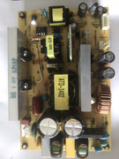
5) Remove the existing Relay
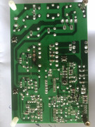
a. De-solder the 4 pins on the bottom
b. Using an exacto blade, cut away the silicon sealer Onkyo uses to hold the relay in place for shipping. If desired, you can recoat the relay with silicon when you are done but I usually don’t bother
6) Remove the existing 150ohm resistor
a. Easier to remove if you cut it off from the top side first
b. De-solder the pins from the bottom and remove the stubs left from cutting
7) Solder in the new parts and reverse the process to reassemble
FIRST – VERY IMPORTANT – unplug the Receiver and let it sit for at least 1 hour to discharge the internal capacitors.
Step 2 – Remove the top cover– 9 course thread screws
Step 2a) Remove the top cover side screws (6)
Note that the top 2 screws go into plastic so do not overtighten when you re-assemble or you will strip the threads.
Step 2b) Remove the top cover rear screws (3)
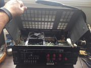
Step 2c) Tilt the rear of the case upwards to disengage the front clasps and remove the top
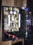
Here is what you will see with the top cover removed
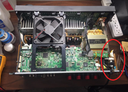
The board you are going to be working on is circled in Red:
The board you are going to be working on is circled in Red:
Step 3 – Disconnect the cables – there are 3 cables that must be detached
Step 3a) – for the 2 locking connectors simply squeeze the lock in and pull the cable free
Step 3a) – for the 2 locking connectors simply squeeze the lock in and pull the cable free
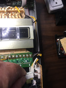
Step 3b) The “push in connector” is located on the top board (HDMI board) and is removed by bracing your finger under the board and using your thumbnail to push down on the edge of the connector. This will release the tension on the spring clips and allow the cable to pull out easily
Step 4) – Remove the power board
Step 4a) – first remove the two screws holding this board on the rear of the unit. These screws are circled in red.
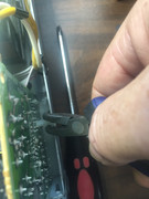
Step 4b) – remove the plastic locking tab that stabilizes the board from the side. If necessary you can spin this tab with a pair of needle nose pliers. I find it easiest if I first squeeze the outside section to clear the tab from the chassis and then work on the tab connection to the board.
The side of the tab that holds the board is shown circled in red below. It can be a little tricky to remove but if you hold the section you just released from the chassis and pull on it while squeezing the board tabs with a pair of pliers, it will pull right out.
Step 4c) you should now be able to turn the board slightly and lift it out of the receiver. It helps if you straighten the cable going to the HDMI board a little to help guide it out of the system.


