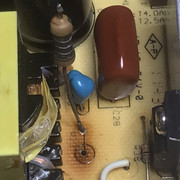
Post by serafis on Jan 22, 2022 0:34:26 GMT -5
Hoping someone can help with this. I am repairing a Pioneer VSX-920K which is going into protect mode with DC output of 7-10V on the Surround-Left (SL) channel. It had a number of other problems which I've managed to fix - details at the end of this post as they may help someone else. But I'm stuck on this last one. I've attached the schematic for the amplifier for this channel.
This is what I know so far:
1. The service manual for VSX-920 is entirely incorrect - it shows a completely different board layout and schematics. The service manual for VSX-1020 seems to be largely accurate for the VSX-920 so I'm working from this.
2. The output transistors Q1202SL and Q1202SL test fine, but I replaced them anyway in case they were 'leaky'. No difference. I also swapped Q1203 with another channel but that made no difference either.
3. I've tested all other components in situ with my DMM, comparing the readings with other working channels. They they all seem OK, except for possibly Q1208, which is showing slightly lower forward voltages on my DMM (B-E and B-C of around 0.645V) than the same transistor in other channels (B-E and B-C of around 6.63V).
4. If I unplug the connector to the DC Protect circuit and speaker relays (CP11, an 8-pin connector, 7 for the 7 channels and 1 for Overload Detect), I can release the protection and the receiver then powers up fine. I can also reset the DC error counts and there are no other errors showing.
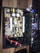
With CP11 disconnected I can then test further as follows, however it's almost impossible to get at the amplifier board when it is bolted to the heatsink and in situ in the receiver and the connection cables aren't long enough for the amplifier board to be removed.
5. When first turned on, the working channels initially show around +47V on CP11, but quickly oscillate and settle to around 70mV before the speaker relays click on. The failing channel also shows around +47V but after oscillating, settles to around 9-10V. It is this DC voltage that will trigger the protect circuit of course.
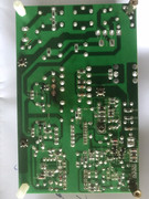
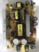
Now in order to check or swap components, the amplifier board needs to be unbolted from the heatsink and bent away to access the rear of the board - this stresses the pins of the transistors bolted to the heatsink, and they will no doubt break if I do this too many times.
So I'd really appreciate any diagnosis of the problem from the above information and the schematic, or suggestions as to what to check for next.
For information, these are the other problems I identified and fixed on this receiver:
When I got it, it was completely unresponsive, with just the HDMI LED flashing at 1-second intervals. Neither Protection Release (Tune Down + Multi-Zone On/Off for 5 seconds) nor Service Mode (Enter + Multi-Zone On/Off for 5 seconds) did anything. I disassembled it completely and cleaned and inspected all boards. This is what I found / fixed:
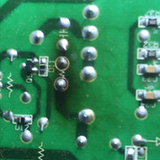
- Dry/loose/cracked solder joints and PCB tracks on the 2-pin Overheat detection socket on the main board. I repaired this, reinforced the tracks with wire and glued the socket in place.
- Dry/loose/cracked solder joints and PCB tracks on a 7805 regulator on the Component Assy board. I resoldered and reinforced with wire.
After this, I could release from protection and power on but it immediately powered off with the HDMI LED flashing again. Tracing the protection circuit, I found that trace #13 of the flat ribbon cable from the Front Panel board board was not making contact with the connection socket on the Digital Assy board. Trying a new cable didn't help, and I had to carefully bend the socket's connector out slightly. After contact was made, I could release Protection mode and enter Service Mode, which showed a DC error count of 255 and a High Temperature error count of 16, but no other errors.
I reset these errors (Tune-Left + Tune-Right, then Enter), powered off and powered on again. This time, the display flashed "Amp Error" and it powered off, and Service Mode showed a DC error count of 1 but no other errors. That's when I discovered the DC output on the SL channel, described above. If I can fix this, then I believe the receiver will be fully functional again!


