Post by tjmotter on May 15, 2022 15:18:01 GMT -5
I noted in a thread on the Audio forum that I had a lightning strike hit my pool area and proceeded to damage about 30 different devices in my house. 4 TV’s, a couple of DVD/BluRay players/Changers, my home security system, my xBox, 3 Ethernet switches, a couple of DirecTV receivers, my Onkyo NR818 Receiver, the controller board in one of my AC/Furnace units and much more. I have gotten most of the devices fixed now and have finally gotten around to repairing my Jandy RS8 Pool Controller. To tide me over, I bought a used unit on eBay but I really wanted to fix up my original controller. It is now working perfectly so I thought I would share what I learned.
For those of you unfamiliar with pool maintenance, it is important to cycle all of the water in your pool through your filter at least once a day. On my system, this is calculated to take 4 hours. I also have a cleaner installed that creeps around the pool sucking any debris into a bag. Attached to my pool is a Spa that also needs to have the water cycled and of course, lighting for the pool and spa. When we first bought this house I was a little concerned over how the previous owner had set things up. He did have a timer that ran the main pump and cleaner but turning anything else on consisted of trying to remember what each of the 8 light switches by the pool did. Making matters worse, there are periods of freezing temperatures in my area which meant that I needed to run outside to switch the motors on when it got cold to avoid freezing the pipes. Even simple things like using the Spa meant figuring out which light switch enabled the heater, turning on the main pump and the Spa pump. Playing with the switches until I found the one that reversed the valve actuators so that the Main Pump would switch from servicing the pool to servicing the Spa so that I could use the heater. Then, figure out which switch turned on the light. After 1 month I decided to buy a Pool control system. I love the Jandy systems so I bought an RS8 with a OneTouch controller that would allow me to program it to control everything from within the house. It also offers the ability to monitor ambient temperature and to automatically turn the pumps on if the temperature approaches freezing. The system is programmable so I have it setup to turn my main pump on for 4 hours every morning, it turns the cleaner (Polaris) on as well (driven by another pump) and it then kicks over to cycle the water in the SPA as well. All in all, a great system that has been working perfectly for 10 years. As some of you will know, most pools will run one of the pool output lines into the SPA so that fresh clean water is cycled through it while the pool is being cleaned (it overfills the SPA and the excess water cascades out of a spillover into the main pool) but this doesn’t pull any water out of the SPA so I like to run it in pure SPA mode for an hour so that the drains suck any accumulated dirt etc. out of the SPA.
So, as I said, the Jandy worked great until the lighting strike and since I had far too many things to fix, I bought a replacement board to use until I could get around to fixing it.
Unfortunately, the replacement board had issues of its own and while it would startup, it would not operate all of the relays. This forced me into the 1st phase if figuring this board out and resulted in replacement of the Darlington driver chip (ULN2803A - TRANS 8NPN DARL 50V 0.5A 18DIP - placed in a socket because it is the most likely to fail) and the FlipFlop (MC74HC374ADWG - IC FlipFlop D-TYPE SNGL 8BIT 20SOIC). I now had one good board to tide me over until I could repair my original. The two parts I replaced are circled in YELLOW in the picture titled: Jandy RS Back Key Components 1).
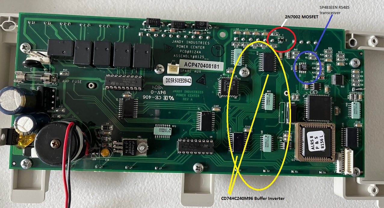
It turns out that my board was pretty bad. The biggest issue was a blown MOSFET (2N7002 - MOSFET N-CH 60V 300MA) that had shorted and the same issue (short on the power rail) on a buffer chip (CD74HC240M96 - IC BUFFER INVERT 6V 20SOIC). After replacing these two parts (the MOSFET is circled in RED and the Buffer is the top one circled in YELLOW in the picture titled: Jandy RS Back Key Components 2) as well as replacing the same two components as the first board, the shorts were gone and the board booted up. The only issue now was that it would not communicate with the remote control unit in the house. I root caused this to the RS485 Transceiver and quickly replaced that as well (circled in BLUE in the picture titled: Jandy RS Back Key Components 2).
Finally, the board worked properly.
These boards are difficult to work on because Jandy coats all of the components with a veneer of some sort. I suspect it is to protect against shorts in the event that the unit gets wet but it makes it very difficult to figure out what parts they are using since the part numbers are pretty much hidden. Making matters more difficult, this veneer literally glues the components onto the board. The way I dealt with this was to first use some solder wick to pull the solder off all the pins of the device I was removing. This also removed the veneer from the pins. Next, I used some CHIPQUICK to coat all of the pins on the device and while keeping it hot by moving my soldering iron between the two sides, I used a screwdriver to pop the chip free. This is an important step to avoid damaging the board. For those of you unfamiliar with ChipQuick, it is an alloy that looks like solder but has a much lower melting point. There are videos on YouTube showing how it works but essentially, when applied across a set of pins, it merges with the existing solder and lowers its melting point giving you 5-10 seconds of time where the pins are free to move. Once you have the ChipQuick molten, it is safe to pry on the chip since it won’t pull up any traces.
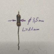
The Jandy RS system consists of a Main control panel that sits near the pump equipment and a remote control device that can be wired or (optionally), wireless so that it can be programmed/controlled from within the house. All 110V and 220V circuits for pumps/blowers/lighting etc. are connected through relays like the one in the picture below titled: Jandy RS Relay. The wire from the relay then connects to the control panel. In theory, if the system was turned off, this should ensure that something like a blown motor or a lightning strike would be essentially isolated from the control panel but when 50,000Volts hits the ground near you electronics, very bad things can happen since up to 90% of the components in any electronics design have one pin connected to ground.
If anyone wants to try to repair one of these themselves, here is some information that might help. The pictures below are:
3) Jandy RS Back Key Components 1: This picture shows the components used to control the devices. The components circled in BLUE control the Valve Actuator Motors and the components circled in YELLOW control the relays. If I had a board that would not operate the JVA Valve actuators, I would focus on the components in BLUE. If I had a board that had 1 or more relays that didn’t turn on (of course only after checking the relay itself to ensure it was working), I would focus on the components in YELLOW. In my case, I had to replace the components circled in YELLOW to repair my first board.
The parts are hard to identify because of the veneer that Jandy applies so below is a list of all the key parts you might need along with links to a source that you can purchase them. Most come from Digikey but Mouser also sells them. Both vendors will also sell you a small package of CHIPQUICK, solder wick and any other supplies you might need.
MC74HC374ADWG
IC FlipFlop D-TYPE SNGL 8BIT 20SOIC
CD74HC240M96
SP483EEN-L/TR
IC TRANSCEIVER HALF 1/1 8SOIC
ULN2803A
TRANS 8NPN DARL 50V 0.5A 18DIP
www.digikey.com/en/products/detail/stmicroelectronics/ULN2803A/599591
HTH
Todd
For those of you unfamiliar with pool maintenance, it is important to cycle all of the water in your pool through your filter at least once a day. On my system, this is calculated to take 4 hours. I also have a cleaner installed that creeps around the pool sucking any debris into a bag. Attached to my pool is a Spa that also needs to have the water cycled and of course, lighting for the pool and spa. When we first bought this house I was a little concerned over how the previous owner had set things up. He did have a timer that ran the main pump and cleaner but turning anything else on consisted of trying to remember what each of the 8 light switches by the pool did. Making matters worse, there are periods of freezing temperatures in my area which meant that I needed to run outside to switch the motors on when it got cold to avoid freezing the pipes. Even simple things like using the Spa meant figuring out which light switch enabled the heater, turning on the main pump and the Spa pump. Playing with the switches until I found the one that reversed the valve actuators so that the Main Pump would switch from servicing the pool to servicing the Spa so that I could use the heater. Then, figure out which switch turned on the light. After 1 month I decided to buy a Pool control system. I love the Jandy systems so I bought an RS8 with a OneTouch controller that would allow me to program it to control everything from within the house. It also offers the ability to monitor ambient temperature and to automatically turn the pumps on if the temperature approaches freezing. The system is programmable so I have it setup to turn my main pump on for 4 hours every morning, it turns the cleaner (Polaris) on as well (driven by another pump) and it then kicks over to cycle the water in the SPA as well. All in all, a great system that has been working perfectly for 10 years. As some of you will know, most pools will run one of the pool output lines into the SPA so that fresh clean water is cycled through it while the pool is being cleaned (it overfills the SPA and the excess water cascades out of a spillover into the main pool) but this doesn’t pull any water out of the SPA so I like to run it in pure SPA mode for an hour so that the drains suck any accumulated dirt etc. out of the SPA.
So, as I said, the Jandy worked great until the lighting strike and since I had far too many things to fix, I bought a replacement board to use until I could get around to fixing it.
Unfortunately, the replacement board had issues of its own and while it would startup, it would not operate all of the relays. This forced me into the 1st phase if figuring this board out and resulted in replacement of the Darlington driver chip (ULN2803A - TRANS 8NPN DARL 50V 0.5A 18DIP - placed in a socket because it is the most likely to fail) and the FlipFlop (MC74HC374ADWG - IC FlipFlop D-TYPE SNGL 8BIT 20SOIC). I now had one good board to tide me over until I could repair my original. The two parts I replaced are circled in YELLOW in the picture titled: Jandy RS Back Key Components 1).
It turns out that my board was pretty bad. The biggest issue was a blown MOSFET (2N7002 - MOSFET N-CH 60V 300MA) that had shorted and the same issue (short on the power rail) on a buffer chip (CD74HC240M96 - IC BUFFER INVERT 6V 20SOIC). After replacing these two parts (the MOSFET is circled in RED and the Buffer is the top one circled in YELLOW in the picture titled: Jandy RS Back Key Components 2) as well as replacing the same two components as the first board, the shorts were gone and the board booted up. The only issue now was that it would not communicate with the remote control unit in the house. I root caused this to the RS485 Transceiver and quickly replaced that as well (circled in BLUE in the picture titled: Jandy RS Back Key Components 2).
Finally, the board worked properly.
These boards are difficult to work on because Jandy coats all of the components with a veneer of some sort. I suspect it is to protect against shorts in the event that the unit gets wet but it makes it very difficult to figure out what parts they are using since the part numbers are pretty much hidden. Making matters more difficult, this veneer literally glues the components onto the board. The way I dealt with this was to first use some solder wick to pull the solder off all the pins of the device I was removing. This also removed the veneer from the pins. Next, I used some CHIPQUICK to coat all of the pins on the device and while keeping it hot by moving my soldering iron between the two sides, I used a screwdriver to pop the chip free. This is an important step to avoid damaging the board. For those of you unfamiliar with ChipQuick, it is an alloy that looks like solder but has a much lower melting point. There are videos on YouTube showing how it works but essentially, when applied across a set of pins, it merges with the existing solder and lowers its melting point giving you 5-10 seconds of time where the pins are free to move. Once you have the ChipQuick molten, it is safe to pry on the chip since it won’t pull up any traces.
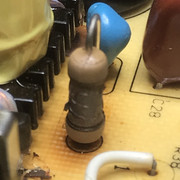
The Jandy RS system consists of a Main control panel that sits near the pump equipment and a remote control device that can be wired or (optionally), wireless so that it can be programmed/controlled from within the house. All 110V and 220V circuits for pumps/blowers/lighting etc. are connected through relays like the one in the picture below titled: Jandy RS Relay. The wire from the relay then connects to the control panel. In theory, if the system was turned off, this should ensure that something like a blown motor or a lightning strike would be essentially isolated from the control panel but when 50,000Volts hits the ground near you electronics, very bad things can happen since up to 90% of the components in any electronics design have one pin connected to ground.
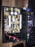
If anyone wants to try to repair one of these themselves, here is some information that might help. The pictures below are:
1) Jandy RS Front Connections: this picture shows the front of the assembled controller highlighting each of the connections
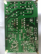
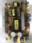
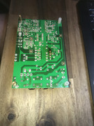
2) Jandy RS Back basic layout: this picture shows the location of the power supply section as well as the CPU and the Firmware chip.
3) Jandy RS Back Key Components 1: This picture shows the components used to control the devices. The components circled in BLUE control the Valve Actuator Motors and the components circled in YELLOW control the relays. If I had a board that would not operate the JVA Valve actuators, I would focus on the components in BLUE. If I had a board that had 1 or more relays that didn’t turn on (of course only after checking the relay itself to ensure it was working), I would focus on the components in YELLOW. In my case, I had to replace the components circled in YELLOW to repair my first board.
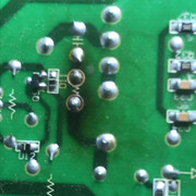
4) Jandy RS Back Key Components 2: This picture shows the parts that blew due to the lightning strike. The two surface mount chips were blown into a short. The voltage regulator measured a short between the output pin and ground when in circuit but was fine when removed. I then chased around the board and found the blown MOSFET (circled in RED) and the blown Buffer chips (20 pin surface mount chips circled in YELLOW). Replacing these two components allowed the board to operate manually but it would not communicate with the remote unit so I had to replace the RS485 Transceiver circled in BLUE.
The parts are hard to identify because of the veneer that Jandy applies so below is a list of all the key parts you might need along with links to a source that you can purchase them. Most come from Digikey but Mouser also sells them. Both vendors will also sell you a small package of CHIPQUICK, solder wick and any other supplies you might need.
MC74HC374ADWG
IC FlipFlop D-TYPE SNGL 8BIT 20SOIC
CD74HC240M96
IC BUFFER INVERT 6V 20SOIC
2N7002H6327XTSA2CT-ND
MOSFET N-CH 60V 300MASP483EEN-L/TR
IC TRANSCEIVER HALF 1/1 8SOIC
TRANS 8NPN DARL 50V 0.5A 18DIP
www.digikey.com/en/products/detail/stmicroelectronics/ULN2803A/599591
HTH
Todd


