|
|
Post by barclay66 on Mar 7, 2016 5:50:00 GMT -5
Hi,
Those TDAs regularly die because of too much ripple on their supply (Pin 9). Replace C125/C25 with some high quality (105Deg/Low ESR) caps. Same values...
|
|
|
|
Post by barclay66 on Feb 4, 2016 5:46:34 GMT -5
You mean, just like Data did? 
|
|
|
|
Post by barclay66 on Nov 16, 2015 8:49:47 GMT -5
Hi,
You're welcome. I wouldn't try to repair this board. The PCB material has a large damaged area that has to be drilled/cut away completely. Otherwise You may have leakage currents where there shouldn't be. And the connector will have to be replaced as its contacts may be burnt and the plastic may be deformed as well. I would use the board as a parts donor only. But verify each part before mounting it somewhere else...
Regards,
barclay66
|
|
|
|
Post by barclay66 on Nov 16, 2015 7:59:52 GMT -5
Hi,
This doesn't look like HV spark damage where only small traces can burn and you mostly see small burning dots over the place (arcs with high voltage but low current). It looks more like an overcurrent event where the vias are burnt away at the location with the smallest diameter because they can't support the amount of current. Maybe someone tried to mount the board at the wrong location and found out using the magic smoke indicator...
Regards,
barclay66
|
|
|
|
Post by barclay66 on Aug 7, 2015 3:13:54 GMT -5
Hi,
I found what's causing the problem. On my computers I use TPLs (Tracking Protection Lists) for IE11 (see: here). Those lists are quite convenient as they allow You to block external content (mostly ads) when visiting web sites. When I deactivate them everything works as described (including file and image upload)...
Regards, barclay66 |
|
|
|
Post by barclay66 on Aug 7, 2015 3:05:14 GMT -5
Hi,
This is just an idea which is based on several schematics for line doublers that I 've been studying. Here's its theory of operation:
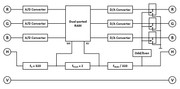
Line-based digitizing of the video signal
The red, green and blue video signal are digitized through individual analog to digital converters. The conversion rate needs to be matched to the input resolution. So if the input format has a horizontal frequency of roughly 16KHz we get 62.5µs for a complete line. If each line has 320 pixels we get 0.195µs per pixel which results in a minimum conversion rate of 5.12 MHz. Going higher will give room for slightly higher input resolutions. Going lower will result in loss of picture information. Ideally the conversion timing would be related to the horizontal sync signal. A/D conversion control isn't shown in the block diagram yet.
Line-based memory (line buffer)
The horizontal sync impulse (indicating the beginning of a new line) is used as a reference for a frequency multiplyer (PLL generator) and its output controls the write enable of a dual-ported RAM. As the name indicates, a dual-ported RAM has two independent access ports to its memory cells. So you can write onto the same cell from one port as you're reading from the other port. In addition, the writing/reading speed at the two ports is independent from each other and limited by the device's general access timings only. So, multiplying the horizontal frequency with the expected number of pixels per line will result in an exact digital copy of a line's content into memory. Therefore we can call it a line buffer. The size of the memory device will be fairly small as we need one byte per colour and pixel only (at a horizontal resolution of 320 pixels we would need 3 x 320 bytes). For reading the memory content at the other port we use another frequency multiplier's output (this time multiplied by two) as a control signal. So each line gets read two times. Maybe the memory will need to be doubled in order to prevent that new input signals overwrite the memory cells before they have been read twice. So the output reading system would toggle between the two line buffers. This would add a lag of one line. What is missing in the block diagram is a more detailed elaboration of the address counter and memory peripherials.
Output signal generation
Once the line buffer is read, three digital to analog converters produce an analog output signal for each color. The conversion rate here is exactly twice as high as on the A/D conversion side. D/A converters with a bandwith of more than 10MHz will be required. Maybe a passive (R2R) version could be suitable. In order to blank each second line (we don't want line doubling but scan doubling!) the memory read control signal is divided by 320 (yielding the new horizontal sync signal, now twice as fast as the input signal) and fed to a two-stage binary counter. It's MSB (most significant bit) output will be toggled at each second line and this signal controls three fast analog switches which connect the video outputs to ground, thus blanking each second line. This part of the block diagram is missing some details like the binary counter and the video output amplifiers.
I can imagine that someone could create this inside some FPGA or similar device but I can't. I would try to build this with conventional hardware...
Regards, barclay66 |
|
|
|
Post by barclay66 on Aug 6, 2015 4:15:50 GMT -5
Hi,
I have an idea for a device which should be able to reduce lag to two lines max.
I've put together a block diagram which shows all functional elements needed. Is there any way of uploading/including an image into a post?
There's an "Add Attachment" button but it doesn't do anything and I don't want to use any external picture hoster...
Regards,
barclay66
|
|
|
|
Post by barclay66 on Aug 5, 2015 14:21:54 GMT -5
Hi,
It really must have something to do with the browser. Interestingly enough, on a different PC with the same OS (Win7 Enterprise) and browser I don't get the green pop ups either.
However, I managed to save the settings using my smartphone and the mobile version of this site.
Thank You!
Regards,
barclay66
|
|
|
|
Post by barclay66 on Aug 5, 2015 2:27:02 GMT -5
Hi,
I don't think that it is 1/3 of a line only.
At 60Hz we have a complete frame every 16,667ms (1/f=T: 1/60=0,01667s=16,667ms).
So if we have a lag of 2ms that will be roughly 12% of a frame (2ms/16,667ms*100=11,999).
At 240 lines per frame this will result in a lag of about 29 lines (240*12/100=28,8)...
Regards,
barclay66
|
|
|
|
Post by barclay66 on Aug 4, 2015 6:47:04 GMT -5
Hi,
Thank You for putting effort into this.
I tried all of Your suggestions but I never got the green "saved" pop up.
Maybe my IE (IE 11) security settings are too restrictive (although Active scripting and Javascript are enabled both).
The system on the "Notification" tab is different from the other tabs. There I do see a grey "Save..." button and it works.
Regards,
barclay66
|
|
|
|
Post by barclay66 on Aug 3, 2015 17:33:35 GMT -5
When you make a change under the notifications tab it is auto saved. Sorry, but nothing is saved. If after changing something I swith to another tab (e.g. "Privacy") and then back it will revert to the previous settings. If fact, when you make a change, there is a green pop up that states "saved". No. Only on the other tabs which all have a "Save settings" button ther will be a banner shown on top of the page indicating success. But the "Notifications" tab doesn't have such a button... |
|
|
|
Post by barclay66 on Aug 3, 2015 2:24:50 GMT -5
Hi,
I haven't counted the number of emails per day. It well may be that it's only one per day. But that's not my point.
The problem is with the menu page for notifications: You can't change any setting because the button "Save settings" is missing...
Regards,
barclay66
|
|
|
|
Post by barclay66 on Jul 30, 2015 14:18:33 GMT -5
Hi,
I find it rather annoying that I get an email whenever someone posts in a thread where I've participated.
There is a page in the profile settings menu where I would be able to change this but this page doesn't have any button for aving the setting.
Can You check this please?
Regards,
barclay66
|
|
|
|
Post by barclay66 on Jul 30, 2015 13:54:25 GMT -5
Are D10, D12 also missing on your board? Nope. |
|
|
|
Post by barclay66 on Jul 30, 2015 10:37:50 GMT -5
Yes,
Mike put in capacitors where the diodes had been. That seems to be a standard procedure on boards he's working on. I too have some MP modded neck boards and there the inductors (FB1 & FB2) were replaced with different ones and the diodes D5 & D7 were replaced with SMD capacitors...
Regards,
barclay66
|
|