nashou
Unmoderated Off Topic
Tech in Training.....
Posts: 1,239 
|
Post by nashou on Mar 6, 2014 19:32:22 GMT -5
Ok back down to 1.xxx voltages
Nashou
|
|
nashou
Unmoderated Off Topic
Tech in Training.....
Posts: 1,239
|
Post by nashou on Mar 6, 2014 19:17:25 GMT -5
It took out R 474 and 475.Those are removed.
I tested R 458, D 409 and D 410 all read ok but will remove them too.
nashou
|
|
nashou
Unmoderated Off Topic
Tech in Training.....
Posts: 1,239
|
Post by nashou on Mar 6, 2014 18:52:15 GMT -5
Working pretty good so far on the VSX parts but that solder flows easy.
I still think I'll have to preheat the Samsung board( Y SUS) I tried there and on the ones with large solder planes it has trouble getting it all but works great on the other points with smaller solder planes.
Nashou
|
|
nashou
Unmoderated Off Topic
Tech in Training.....
Posts: 1,239
|
Post by nashou on Mar 6, 2014 18:48:37 GMT -5
Ok DC went down to 1.5 to 1.7 volts.
Still wont stay on. Decided to test DET points and then Smoke and flame from R 483 !1 it took out Q 416 and 422. I did not test DC after that!!
Crap!!! I have more so... but CRAP!!
And I lost one of the diodes somewhere!! Crap!!!
Nashou
|
|
nashou
Unmoderated Off Topic
Tech in Training.....
Posts: 1,239
|
Post by nashou on Mar 6, 2014 18:21:37 GMT -5
Still DC but now its bouncing around from 26.xx to 28.xx etc.
Nashou
|
|
nashou
Unmoderated Off Topic
Tech in Training.....
Posts: 1,239
|
Post by nashou on Mar 6, 2014 18:15:09 GMT -5
Removed 404 still DC
Onto 410
|
|
nashou
Unmoderated Off Topic
Tech in Training.....
Posts: 1,239
|
Post by nashou on Mar 6, 2014 17:37:58 GMT -5
Ok Mac, we are on to something.
Remove the first two resistors and DC went down to 29.xx on all channels.
Onto the next parts unless I should wait for your response?
|
|
nashou
Unmoderated Off Topic
Tech in Training.....
Posts: 1,239
|
Post by nashou on Mar 6, 2014 16:39:40 GMT -5
Just got this from B+D on Ebay. Since I'll be doing a lot of desoldering and the EPM chips on my Plasma have a huge GND plane around it getting the high temp solder to flow easily enough to remove it with solder wick or the old bulb type suction just won't cut it. I read and did a lot of research on Desoldering guns and for the money this seemed the best bet. Will try it in an hour or so while it warms up from being outside on my porch all day. 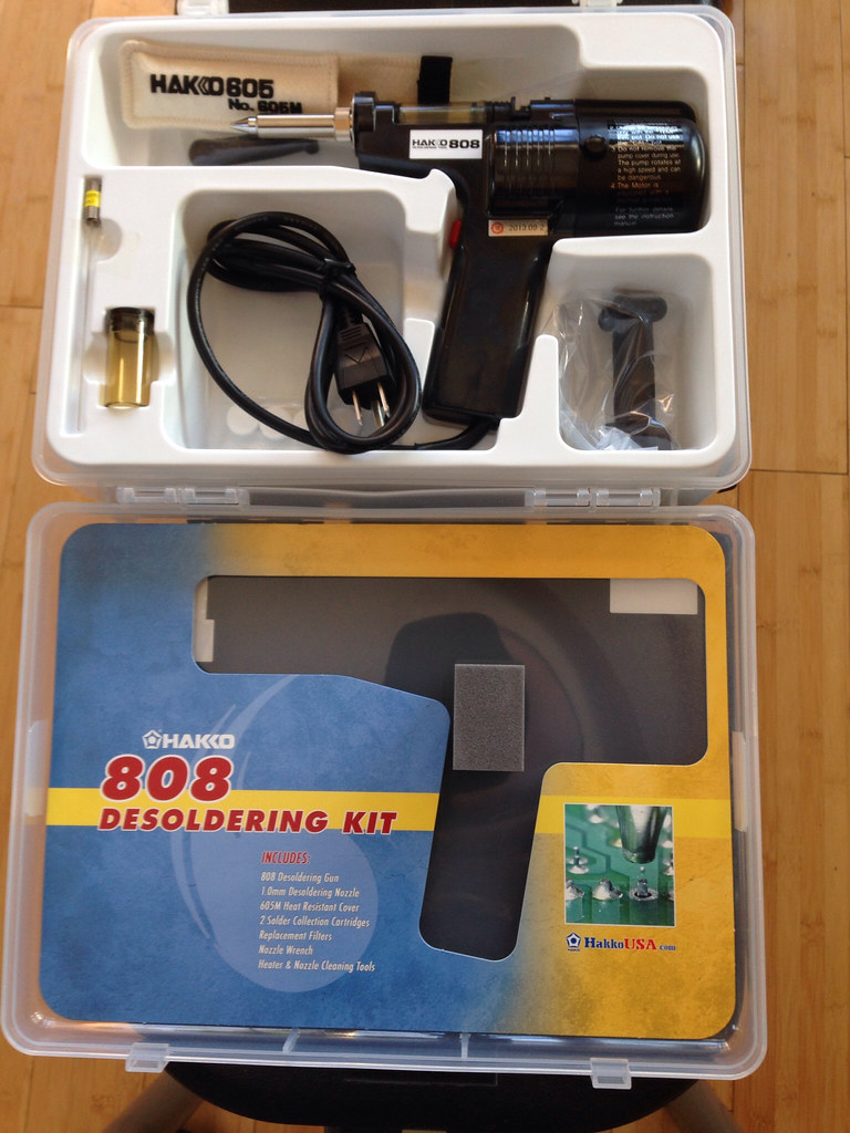 For 178 bucks it seems more reliable than the 130 dollar Aoeyu version. And with the lifted solder circles on the VSX 822 amp i want to use something that will remove more solder and damage the through holes less. This should be the final piece of equipment i'll need. ..........hopefully  Athanasios |
|
nashou
Unmoderated Off Topic
Tech in Training.....
Posts: 1,239
|
Post by nashou on Mar 5, 2014 22:27:17 GMT -5
they are all 54.6 the last one is 54.5 that is the white one. Just to verify, there are only 5 pins on this connector, correct? yes the connector with the Signal's for the channels. 5 wires. I'll work on it tomorow. I do hate how delicate these boards are , traces are easily lifted at the through holes. Nashou |
|
nashou
Unmoderated Off Topic
Tech in Training.....
Posts: 1,239
|
Post by nashou on Mar 5, 2014 21:47:53 GMT -5
they are all 54.6 the last one is 54.5 that is the white one.
|
|
nashou
Unmoderated Off Topic
Tech in Training.....
Posts: 1,239
|
Post by nashou on Mar 5, 2014 20:48:57 GMT -5
You should be using highgnd for your neg probe. CP403, pins 7,8,9. Recheck all your reading! Same results on all readings The Signal lines and the Protection Lines. Nashou |
|
nashou
Unmoderated Off Topic
Tech in Training.....
Posts: 1,239
|
Post by nashou on Mar 5, 2014 20:04:06 GMT -5
Just to add I have no heat sink on amp.
And is it ok I am using the chassis for GND when testing volatages?
Nashou
|
|
nashou
Unmoderated Off Topic
Tech in Training.....
Posts: 1,239
|
Post by nashou on Mar 5, 2014 20:00:43 GMT -5
Those are protection transistor for thermal protection. There is a resistor across emitter and base so you may be reading that. I do not see where they would put B+ on the outputs. Also unlikely they would all blow out. Since the same DC is on all lines it has to be something common with every channel. Can you DC test all pins on CP404 to see if it is more then 1 protect line being turned on? Sure. I did that before but now all parts are back in and seem ok. DC DET 4 is 1.277 DC DET 3 is 1.523 ASO DET is 0 RADI Thermal is .255 TR Thermal is .257 |
|
nashou
Unmoderated Off Topic
Tech in Training.....
Posts: 1,239
|
Post by nashou on Mar 5, 2014 19:13:52 GMT -5
Ok So I put The parts in and still the same.So I saw there are some SMD Transistors on the back side of the board. And some have shorts between the legs on the same side of the SMD not sure if this is normal or not.
These are Q 403, 415, 427, 439 and 451 all have the HIGH B+ line to them and all the test points like TP401 have the +53 VDC on pin 1 and 3 .
So if these went bad would that cause the measurements I am having?
I need to remove one and test out of circuit to be sure of course as I can not see anything that would give me a .000 on my diode test for the two pins but read ok if i test the single pin to either of the pins on the same side.
I think they are all 2N5401S parts
SO I looked up the data sheet and the short is between the Emitter and base.
Nashou
|
|
nashou
Unmoderated Off Topic
Tech in Training.....
Posts: 1,239
|
Post by nashou on Mar 4, 2014 14:58:23 GMT -5
Just yank the right one out of one of those 1021's you bought. I didn't even think of that!! I'll order some anyways and pull one out later tonight when I get home from work. |
|


