|
|
Post by justgreg on Feb 26, 2015 18:19:04 GMT -5
Hi Mac and thanks for the quick reply.
That's a fine question. I looked with a magnifying glass and when that did't work I went looking for my jewelers loupes and failed. Having cataracts doesn't help much either. lol
I'll find a way to get it and check back.
|
|
|
|
Post by justgreg on Feb 26, 2015 16:37:11 GMT -5
Ugh....damn flu.
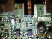
The output side is .025 and a solid tone using a Fluke 233.
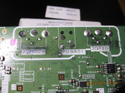
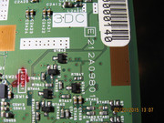
Theres a glass diode just below the fuse, ID#D9A01 that's got a solid tone on both sides on diode setting and also produces a solid tone on ohms setting.
|
|
|
|
Post by justgreg on Feb 25, 2015 14:22:10 GMT -5
Thank you for replying and it's good to be back!
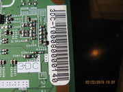
Sorry bout that...yes it is F9A01. The fuse looks cooked because I started to heat it to remove it and thought I'd best take pix to post with it in place. It had no obvious blown appearance before that. As far as I can see that's the only fuse on the board...that's marked anyway. I was thinking of using a selectable voltage power supply from Rat Shack set at a lower than normal operating requirements to send a low voltage tattle tale down stream and probe components until I lost it on one side of a component. Dang multi layer boards make that a crap shoot without a schematic and at my skill level. Any thoughts on trying that?
The left side of the fuse is the downstream side btw...if that means anything.
Thanks Mac!
|
|
|
|
Post by justgreg on Feb 24, 2015 16:37:46 GMT -5
|
|
|
|
Post by justgreg on Feb 24, 2015 16:33:31 GMT -5
Hi Folks
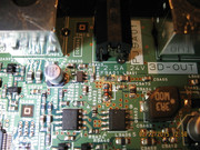
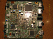
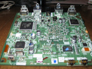
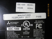
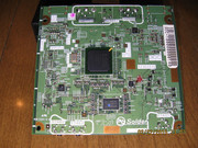
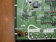
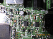
I bought a broken/not working Mitsubishi 3DC-1000 that won't power up. The wall wart is OK and outputs the required voltage. When I opened the device I found the SMD SOT-23 (?) fuse open. The downstream side of the fuse tests out as shorted to ground. I've visually inspected both sides of the board for obvious blow components and performed a quick and simple test of all the non-SMD electrolytic capacitors using a DMM. I have a cap tester but haven't used it yet. I haven't found a single shorted cap so far with the DMM. Please note I just got the 3DC the other day so haven't done every test I can with the few items of test equipment I have at my disposal.
My old digital camera isn't that great at macros but I snapped some pix as close to the power entry section of the board as possible, as well as pix of the back side and any labels and silk screened markings. I haven't been able to find any stories of anyone fixing one of these which is odd given the current price of a replacement 1000 series kit.
Some dry but relevant early 3D history and info:
Odds are against me using this model with my Samsung HL67A750 DLP TV because Mitsubishi released the 3DC-100s after the release of the 3DC-1000 to specifically support Samsung DLP TV's. The 100s is the exact same device as the 1000 but Mitsubishi changed the software of the 1000 kits to prevent them from working with Samsung DLP's....money donchya know. Seeing as Samsung turned their backs on owners of checkerboard output 3D ready sets by not providing any adapters Samsung owners had no choice but to turn to Mitsubishi and pay through the nose for a checkerboard converter.
Panasonic released several models of BluRay players with checkerboard as an output option but that doesn't address the need for a converter for 3D cable/satellite or gaming. I want those capabilities even if I have to buy a Gefen HDMI detective to use with the 3DC-1000 to 'spoof' the TV into thinking it's a Mitsubishi 3D ready checkerboard only set. Given the still very high price of a 3DC-100s 3D kit for Samsung sets (~$300) the Gefen spoof if a viable alternative. The problem with that plan is finding the correct model Mitsubishi EDID and getting it into the Gefen. But...one thing at a time as the saying goes.
Let me know if I can provide additional info. I'd really like to be able to fix this but the first order of business is finding a schematic. Even then I may have to send it to someone with higher level skills and the required test equipment.
|
|
|
|
Post by justgreg on May 27, 2014 2:47:14 GMT -5
I haven't attached a fan because the chip is quite small and truthfully I haven't had time to either locate one with a heatsink, or to fabricate a remote fan and ductwork. There are many possible ways to provide active cooling however I believe based on my experiences with this chip/board, and the 100's of failures reported widely across the internet that the problem lies with the solder and/or BGA manufacturing process. I'd hate go through all the trouble to provide cooling only to end up back at square one. The system has been quite stable for weeks now but when it fails again (I have no doubts it will), I'll have the chip reballed and be done with it.
|
|
|
|
Post by justgreg on May 16, 2014 7:12:25 GMT -5
Ok. Here we are at May 16 and I've had to put heat to the DTS chip. So although my home brew attempt at a lasting fix worked for a couple months, it shouldn't be considered a permanent repair if you follow my procedure. There are many variables involved but the biggest consideration should be given to the quality of the solder used by the manufacturer, and the BGA process itself.
Because the HDMI boards are becoming scarce due to repair shops buying up all available boards to fix and sell, you'll have to determine if you want to DIY reflow or pay them the $80-ish for one they've repaired. Some repairers are installing a daughter board at the time of repair that's supposed to enhance the boards capabilities so if you have ~$80+shipping, that may be the way to go. Keep in mind not all repair shops are created equal so ask about a warranty if you either send them your HDMI board or buy one they have ready to ship.
|
|
|
|
Post by justgreg on Apr 21, 2014 13:51:17 GMT -5
Well doesn't that just suck raw PlayDough™ balls!
I know the 'gunpowder' smudging well. In dark scenes the affected area of the display panel doesn't refresh or decay (?) fast enough so when the image calls for bright, such as white, it takes time for the black streaking to decay off. From what I've learned that's the indication of a panel that's reached EOL. Seeing as the entire thing went belly up that's a moot point I 'spose.
I dunno....I think if it were me at this point I'd be hard pressed to continue investing time and money in it but I DO totally relate to the male ego involved with 'winning'. lol
|
|
|
|
Post by justgreg on Apr 6, 2014 11:29:20 GMT -5
Ok, I need to be more thorough!!!! I found another connector on the Logic board I did not have connected. I powered it up and hit the menu and got the menu from what I can see. not sure how clear it is. I need the stand for this thing!!! But I think its ok and might just need adjustments for the YSUS . Once I get the Stand I can test better. Athanasios Hate it when that happens! Sounds like you're on the home stretch. Yeah plasma's are deceptive in how much they weigh. I was really surprised how heavy they are when I lifted it into my truck with the guy I bought mine from. Have you ever looked into making a rotary generator from rewired whirlpool washing machine motors? I believe the motors are made by Panasonic. Google the youtube vid if you have a minute. You can generate 120v by spinning it with a finger! |
|
|
|
Post by justgreg on Apr 3, 2014 14:56:11 GMT -5
And you'll have the time to put that lifted trace issue to rest so it stops being a factor in your diagnostics. lol
Are you going to add active cooling to each IPM before you button it up?
|
|
|
|
Post by justgreg on Apr 2, 2014 23:44:51 GMT -5
Man the way this thing is fighting you reminds me of my ex wife...without the alcohol.  I guess I got off light with my plasma only needing 2 IPM's. Yeah I'd make low offers on those boards too, especially if you've never done the IC R&R before. Welp, on to the next chapter! Rock on bro. |
|
|
|
Post by justgreg on Apr 2, 2014 15:36:57 GMT -5
Thanks for the kind thoughts crabb. The first 2.5 weeks post surgery were from hell. End of healing is around 6 months which is when the bone stimulator I wear 2hrs a day should have done all ot can do. I'm a journeyman level mechanic and with reduced flexion I'm not sure if I'll be able to return to that field. Scary thought to think about not earning what I can demand.
Anyway, to get BOT, cash is tight right now but I'll def keep this in mind. The reviews of it released at the time the pj came out said the image was a bit soft but hey, umma CRT-er and dig the film noire look. Not everything has to be so sharp it slices through your retinas.
Mac's hit the nail on the head again as usual in that summer is coming and after the rough winter we've all had there will be more than usual maintenance to attend to.
I'll msg ya my email addy if you want to send the SM.
|
|
|
|
Post by justgreg on Apr 1, 2014 23:08:24 GMT -5
In over your head?...nah. Overworked and stretched too thin?...sure sounds like it. I'm 4 weeks post spinal fusion surgery so all I can do is look at my lawn and everything that needs to be done. It's going to be a hot mess this summer.
I know there's a lot more to it than a simple convergence adjustment like with CRT but dang the image looks awesome except for the vertical lines that are being generated. I wish I could find a good working SM to follow along! Yeah the first 10 pages of the SM discuss several memory reflashing/update techniques and the requirements for doing so.
I sold my Quee but the rest of the theater is intact... and now you have me thinking about a digital alternative (again!) Dang you! lol I do miss having my mancave wanna-be hideout though.
|
|
|
|
Post by justgreg on Apr 1, 2014 13:36:11 GMT -5
Well that's a drag. I'm learning too so pardon the following questions....
Could there be a short on one of the output pins at the IPM(s)? I mean, it sounds like you have good voltage going into the IPM but somewhere down stream of one of the outputs there's a short to gnd?...or possibly input voltage goes high after the set is powered on?
Out of curiosity, are there any electromechanical relays in this set?
And the fuse that blew...with no fuse in the holder you get no short to gnd on either side? Would it be a good thing to use lower rated fuses the next time you power up after installing new parts?
Did you happen to check each IPMs pinouts for shorts to gnd when you had the IPM's out?
I would hate to give up on it also if it were me. I guess if you can justify the time and expense for the greater good to learn it's cool but at some point I personally would have to consider any more money to be good money thrown at a bad cause and order new boards and accept the knock to my ego. But that's just me. lol
We're rootin for ya bro!
|
|
|
|
Post by justgreg on Mar 31, 2014 22:30:49 GMT -5
Ooopsie.
So the heatsinks are soldered to the PCB? I watched a pro changing IPM's and the set he was doing was set up like the Insignia I have in that the heatsink was screwed to the IPM and then the IPM was soldered to the board. He used a heatgun to the back of the board with the IPM face down and when the solder was molten he used a vacuum desolderer, then the chip just stayed on the work mat when the PCB was lifted. Wish I'd seen the vid before I battled with mine.
|
|