|
|
Post by Casethecorvetteman on Oct 1, 2015 7:27:10 GMT -5
Try setting that jumper on the system board and see if the issue does what i said it would.
|
|
|
|
Post by Casethecorvetteman on Sept 30, 2015 5:10:43 GMT -5
Now you mention it I did have it too. With a different Moome I had reboots during the handshaking of the Moome. Most likely your smps is the problem. Id be reluctant to believe that at this point. A faulty SMPS probably wont be making the set do what it is. Looking on the SMPS 2, there is a range of LEDs that indicate voltages are present, pulling the board out if you need to and see which ones indicate what. The newer style boards have surface mount LEDs, the older style has small round LEDs. Ive had an issue with the SMPS causing a fan fail shut down, but youll get a visual indication on screen for that. Start with that EHT as i said, then while doing that look at the SMPS 2 LEDs, i doubt youll see an issue there. A sure test of the system board is to set the jumper marked "W2, FORCE SMPS ON". Set that jumper on, turn on the set with a source you know works, and wait for shut down. The set will 'partly' shut down, as in convergence and focus etc will go to complete neutral, but the image will remain. That is a certain system board failure in my experience. |
|
|
|
Post by Casethecorvetteman on Sept 30, 2015 4:52:35 GMT -5
There is also diagnostics in the menu's. red led on smps2 should be on when scan failure. red led on horizontal too when that unit fails. Do not seem to see any red leds lit on the smps. I will try the RGB switcher, Case the corvette man seems to have this same issue with his cinemax. The switcher was not the issue, although the issue did change with that swap, as it did with a different MOOME. That issue was traced eventually to the system board. Start with the EHT and see if that light comes on. From there, you could try swapping the system board, it may be the issue, and worth a look later. |
|
|
|
Post by Casethecorvetteman on Sept 30, 2015 4:48:18 GMT -5
If the EHT fails the set will shut down, but there will be a red LED on the EHT board if it does, and if it does, the quad is likely at fault.
I have had this issue where the EHT would come up for as long as one minute, and then picture would rapidly collapse with a crackle sound. That fault was the quad, however dont rule out the splitter.
Turn on the set with the rear cover open, looking at the EHT board, and see if that red light comes on. At this point id be looking to that. Rule it out, then we can go from there.
|
|
|
|
Post by Casethecorvetteman on Sept 24, 2015 4:43:33 GMT -5
Hahaha!!!
|
|
|
|
Post by Casethecorvetteman on Sept 23, 2015 4:43:33 GMT -5
I saw your post there and was going to send you here, but i never got back to it! Sorry bout that, but you made it here anyway  |
|
|
|
Post by Casethecorvetteman on Sept 18, 2015 5:34:32 GMT -5
This setting at the top:  Turn it on. |
|
|
|
Post by Casethecorvetteman on Sept 18, 2015 5:27:13 GMT -5
On that red grid, that looks like N/S Bow and a little bit of N/S Key. Should be minor fix. Bingo Mastertech! I did a test to extremes values of top and bottom BOW. The blue and red grids should follow the green when we set the KEY and the BOW. Well ... the blue follow it correctly, the red does not move. What is the board responsible for these adjustments? Look at the pictures below. GREEN ONLY  BLUE ONLY 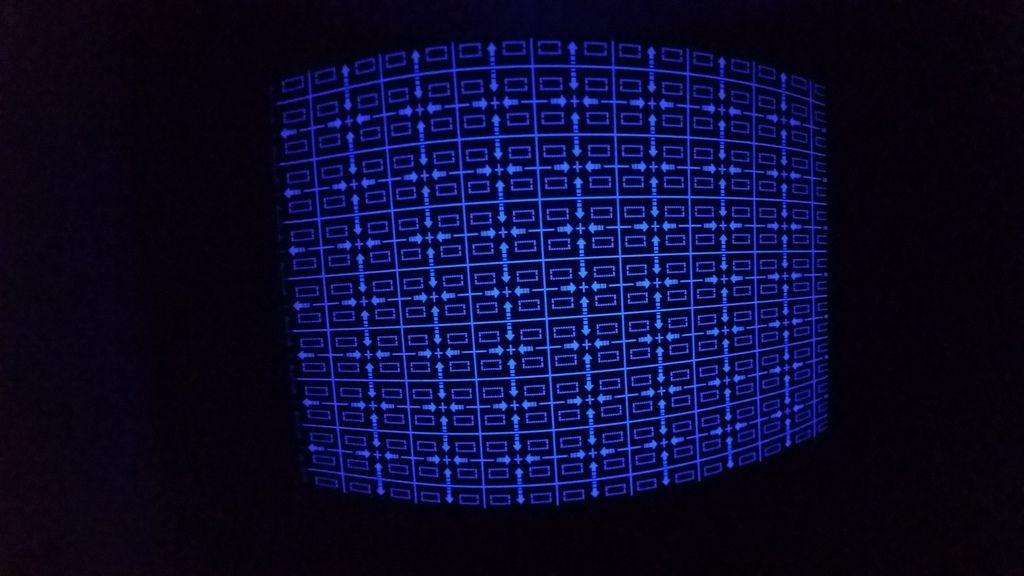 RED ONLY  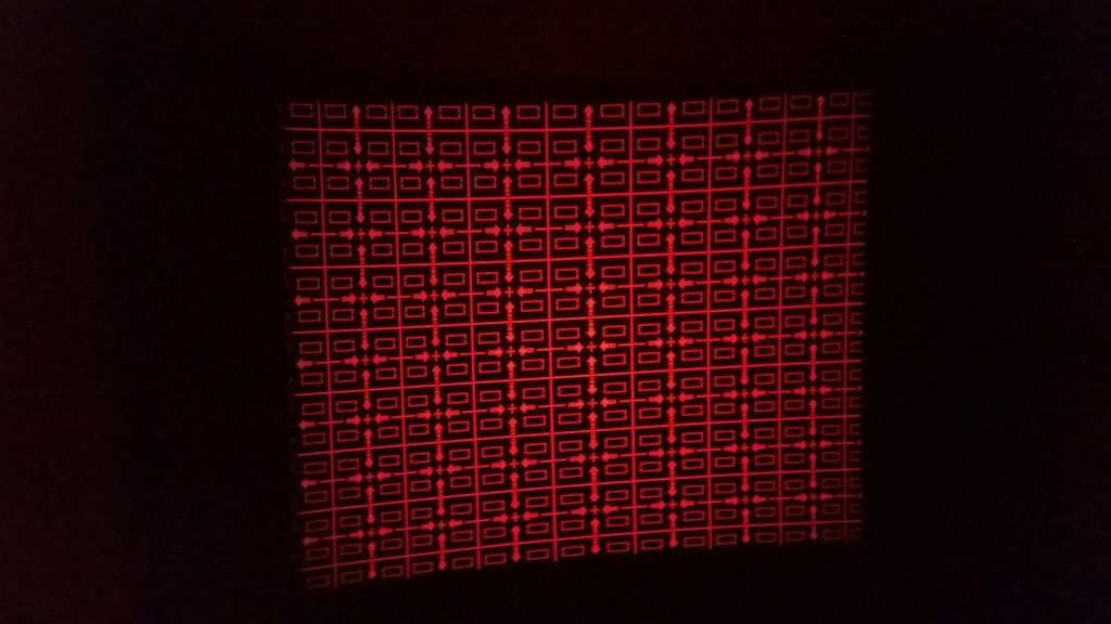 GREEN AND RED 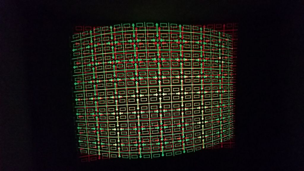 When you say the red doesnt move, are you saying it doesnt move at all or doesnt move enough? do you have the green convergence setting turned on or off? |
|
|
|
Post by Casethecorvetteman on Sept 18, 2015 5:23:14 GMT -5
The vertical board makes the preparation for the coarse east west corrections. No idea further. There are also screws on this board for some settings too. |
|
|
|
Post by Casethecorvetteman on Sept 18, 2015 5:21:43 GMT -5
On that red grid, that looks like N/S Bow and a little bit of N/S Key. Should be minor fix. The problem on these is they only have that setting for green, the red and blue are done via something very simular to point convergence on the XG. |
|
|
|
Post by Casethecorvetteman on Sept 18, 2015 5:16:38 GMT -5
how much digital adjustment are you using for the vertical centre? They should be at or close to 49, because there are adjustment screws for that to line up the centre lines of red and blue with green, and there is also vertical size adjustment screws too.
Set those screws to perfect prior to any digital adjustments, then use the width coils to set red and blue widths to the same as green.
From there, you should need no coarse raster shift in the vertical plane and only 1 or 2 steps of fine raster shift, set the coarse horizontal raster shift of red and blue to match green centre as close as you can, then perfect it with fine raster shift. All the vertical adjustment of the middle section should be pretty near perfect fron adjusting the pots on the board in the rear of the set.
Using the coarse convergence of red to green, you should be able to get everything pretty close, set it to where each zone is closest to aligned in the whole zone, then finish with fine adjustment.
From your pictures it looks like either the screw adjustments are too far out of range, or the yoke is not tight and straight on the tube neck. The way it is i can be sure if the side of the red tube that is distorted is directly beside the green or closest to the projector frame, it may also be worth checking to be sure the green tube is fitted with the correct green tube yokes, as that may have an impact, the screw clamps should have their black wire connected to them and no wires wrapped around them as this could possibly cause current to flow in the clamps, which will produce a magnetic field and influence the beam. It is unlikely for that to be the issue, but i believe it is possible and should be checked.
Start with the adjustment pots, you can set the green up via digital settings, then use the pots to get red and blue as close as you can.
The best way to be sure the red and blue will be centre of their tube faces is to move the red and blue images to centre of their faces, align the sides of red and blue with the green, tilt the tubes, focus lenses and adjust width coils so the size is correct, ignore the middle because youll move that after youre done. When the image on red and blue is centre of their faces, the SIDES of the image must line up with green. When you align the centre again, you will need to align the sides, which will bring them back to the same place and hence, a perfect image position on the tube face.
|
|
|
|
Post by Casethecorvetteman on Sept 16, 2015 3:35:31 GMT -5
If you swap them there and the blue is now distorted, its either the cable, or its the CPU board. I doubt it will be the cable.
If it still remains on the red, the problem will be either the convergence board or the connections between there and the yoke.
Very good chance it will be the CPU board.
|
|
|
|
Post by Casethecorvetteman on Sept 16, 2015 3:31:19 GMT -5
Yes, thats the one  |
|
|
|
Post by Casethecorvetteman on Sept 15, 2015 18:34:22 GMT -5
Perhaps very bad astig magnet adjustments? Its either be the convergence board or the system board, swapping the green and red connections between system board and convergence board should tell which is at fault. |
|
|
|
Post by Casethecorvetteman on Sept 15, 2015 3:16:33 GMT -5
He means plug the red covergence yoke into the blue outputs to see if its the board or the yoke.
Check for bent pins too.
|
|


