|
|
Post by mastertech on Jul 9, 2015 12:20:19 GMT -5
Ok, 7.4v drop may be exceptable with the battery. We will just remember this.
So, you did not hear the click and the red led does not come on with the SMPS installed, correct?
|
|
|
|
Post by Decibel on Jul 9, 2015 12:36:14 GMT -5
Ok, 7.4v drop may be exceptable with the battery. We will just remember this. So, you did not hear the click and the red led does not come on with the SMPS installed, correct? With smps no click and standby-led bright in green. |
|
|
|
Post by mastertech on Jul 9, 2015 12:38:37 GMT -5
I have to run out for a few hours but I want to keep you going while I am gone. I assume the answer to my last question was "correct"? If so, you can now move to the SMPS. On the sub board, locate jumper pins J30. If there is not a jumper connector on there, find one and put it on.
Then locate the green led, D451. Install the SMPS and all other boards in the projector and turn it on. Does the green led come on?
If not or it is dim then you have to diode test D450 for leakage. If none then you have to change C450 and C451, even if it is a newer supply. because if this does not bring the ++9v back up then we have to continue diagnosis to find out why.
I'll check back in a couple hours. Hopefully you will have all this done by then. It should not take long.
|
|
|
|
Post by Decibel on Jul 9, 2015 14:02:43 GMT -5
I have to run out for a few hours but I want to keep you going while I am gone. I assume the answer to my last question was "correct"? If so, you can now move to the SMPS. On the sub board, locate jumper pins J30. Ok Yes but standby-led bright green every time I turn on the projector, always. Diode D451 when prwer on projector brigh green always. |
|
|
|
Post by mastertech on Jul 9, 2015 14:40:14 GMT -5
Can you measure the voltage on both sides of F450 on the sub board while the projector is on? Neg probe on chassis ground then check both sides with positive probe.
|
|
|
|
Post by Decibel on Jul 9, 2015 15:07:28 GMT -5
Can you measure the voltage on both sides of F450 on the sub board while the projector is on? Neg probe on chassis ground then check both sides with positive probe. Seeing Front PCB from service manual. Pin left 14v Pin right nothing |
|
|
|
Post by mastertech on Jul 9, 2015 15:13:19 GMT -5
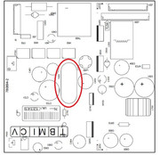
This is F450 in the red circle. Is this where you are testing?  |
|
|
|
Post by Decibel on Jul 9, 2015 15:27:08 GMT -5
Yes
|
|
|
|
Post by mastertech on Jul 9, 2015 15:28:21 GMT -5
Then that fuse is blown. Take it out and diode test it with your meter. It probably shows open.
|
|
|
|
Post by Decibel on Jul 9, 2015 15:32:30 GMT -5
|
|
|
|
Post by mastertech on Jul 9, 2015 15:38:48 GMT -5
Just for the heck of it, while everything is still installed and connected, take your meter and put it on diode test and test between the "0v" side of F450 and chassis ground and give me the reading.
|
|
|
|
Post by mastertech on Jul 9, 2015 15:39:49 GMT -5
Try with test probes both ways and give me both readings.
|
|
|
|
Post by Decibel on Jul 9, 2015 15:45:24 GMT -5
Try with test probes both ways and give me both readings. Ok tomorrow I will do the tests that you ask, now I'm going to bed  |
|
|
|
Post by Decibel on Jul 10, 2015 8:56:36 GMT -5
Well just repeated some tests.
Power on
Meter DC 20v
Black probe to chassis
Red probe to pin "0v" = 0v
Red probe to pin "14v" = 14v
Power on
Meter DC 20v
Black probe to pin "0v"
Red probe to pin "14v" = 14v
Power off
Meter diode test position show always "1" when ...
- Black probe to chassis and red probe to pin "0".
- Black probe to chassis and red probe to pin "14v".
- Black probe to pin "14v" and red probe to pin "0" and vice versa.
|
|
|
|
Post by mastertech on Jul 10, 2015 9:22:59 GMT -5
Replace the fuse and try turning it on and see if the fuse blows or not.
|
|