|
|
Post by Decibel on Jul 11, 2015 10:58:20 GMT -5
But I've already replaced C450/C451 with absolutely new pieces.
|
|
|
|
Post by mastertech on Jul 11, 2015 11:05:26 GMT -5
And for future reference, we could of started all our testing at this fuse, 12 pages ago, lol. This would of told use what we needed to know back then. Unfortunately I do not know the layout of the machine and only have schematics to go by. But we can all note this for future reference. If I get some time and will make a note of this test and post it in the Barco 909 service manual section so it will be easy to find. But I will wait till the conclusion so it will be a good reference.
|
|
|
|
Post by mastertech on Jul 11, 2015 11:08:12 GMT -5
But I've already replaced C450/C451 with absolutely new pieces. Oh, ok. was not aware. Then lets do some testing and see what we can find. On the sub board, locate C400. Probably a small SM and not polarized. Set meter on DC voltage and turn on projector. Test across the cap and you should get around 300v. Let me know what you get. |
|
|
|
Post by Decibel on Jul 11, 2015 11:47:16 GMT -5
But I've already replaced C450/C451 with absolutely new pieces. Oh, ok. was not aware. Then lets do some testing and see what we can find. On the sub board, locate C400. Probably a small SM and not polarized. Set meter on DC voltage and turn on projector. Test across the cap and you should get around 300v. Let me know what you get. I was no able to check 300v I'm afraid to take electric shock  However C400 is not a smd cap but big round red element (ceramic?) near diodes. See the pictures posted by Hulio at post number 29 Other thing ... the diode D451 show pulsating brightness as you said in previous post. |
|
|
|
Post by mastertech on Jul 11, 2015 12:43:27 GMT -5
Then you will have to test the 300v at connector J3, pins 1 and 4. Just don't touch anything with your bare hands. 300v is nothing.  Just keep hands clear. |
|
|
|
Post by Decibel on Jul 11, 2015 13:26:17 GMT -5
Then you will have to test the 300v at connector J3, pins 1 and 4. Just don't touch anything with your bare hands. 300v is nothing.  Just keep hands clear. Yes there is 300v in pin 1 of th J3 connector. |
|
|
|
Post by mastertech on Jul 11, 2015 15:15:36 GMT -5
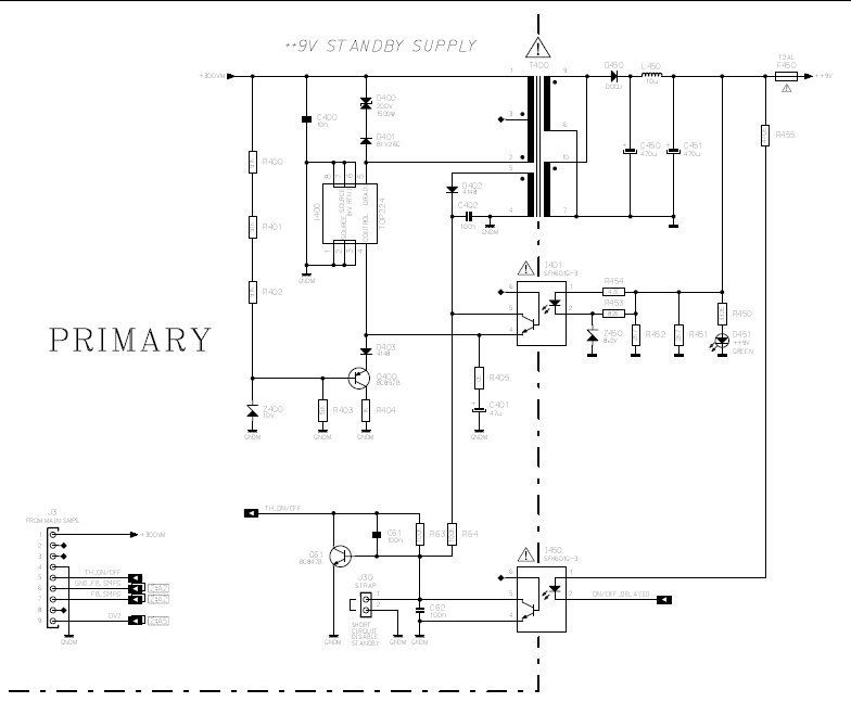
Ok. So now you are going to have to test some individual components. I would suggest just diode testing all the diodes in that circuit but R405 and C401 concerns me. You could do a quick diode test and see if any show leakage but if they are looking ok then I would check R405 for 0 ohm and also replace C401 and test supply for function.
Your circuit is working, it is just not being regulated properly. So I would not expect a completely failed part.
Also, I would not put the fuse (F450) back in just yet. Just do your testing on the fuse holder pin that was getting some voltage. Until this circuit is running properly I would not take the chance of sending to much voltage out through the 9v line.
|
|
|
|
Post by Decibel on Jul 11, 2015 15:19:09 GMT -5
The point of the situation ... Now we know that main board of SMPS provide 300v to sub board where is a circuit (show below) that generate ++9 standby voltage.  Seems that somewhere into this circuit there's a bad component because the ++9v voltage drops at 3v. My question: it's possible that also SMPS of my friend have same issue? Two different boards from two different projector. It's really incredible. |
|
|
|
Post by Decibel on Jul 11, 2015 15:23:26 GMT -5
We wrote togheter  tomorrow I will check the components that concerning the ++9v circuit. Especially those that you mentioned. |
|
|
|
Post by Decibel on Jul 12, 2015 9:54:02 GMT -5
You could do a quick diode test and see if any show leakage but if they are looking ok then I would check R405 for 0 ohm and also replace C401 and test supply for function. I pulled all boards except PFC (and SMPS obviously) Removed F450 fuse, inserted test wire to pin before fuse. Replaced C401 with new piece 47uF 50v Checked R405 and also ALL smd resistors of ++9v circuit. Nothing blown. Checked ALL diodes of ++9v circuit. Nothing blown Result at output ++9v pin = around 3v |
|
|
|
Post by mastertech on Jul 12, 2015 13:51:24 GMT -5
What company do you order your electronic parts from?
|
|
Deleted
Deleted Member
Posts: 0
|
Post by Deleted on Jul 12, 2015 14:23:05 GMT -5
The PFC also uses the 9V.
|
|
|
|
Post by Decibel on Jul 12, 2015 14:26:20 GMT -5
The PFC also uses the 9V. But smps subboard generate ++9v source. |
|
|
|
Post by Decibel on Jul 12, 2015 14:26:59 GMT -5
What company do you order your electronic parts from? Farnell |
|
|
|
Post by mastertech on Jul 12, 2015 14:35:06 GMT -5
The PFC also uses the 9V. Yes it does. But when F450 is removed, PFC is no longer in the equation. |
|