Deleted
Deleted Member
Posts: 0
|
Post by Deleted on Aug 16, 2015 1:36:11 GMT -5
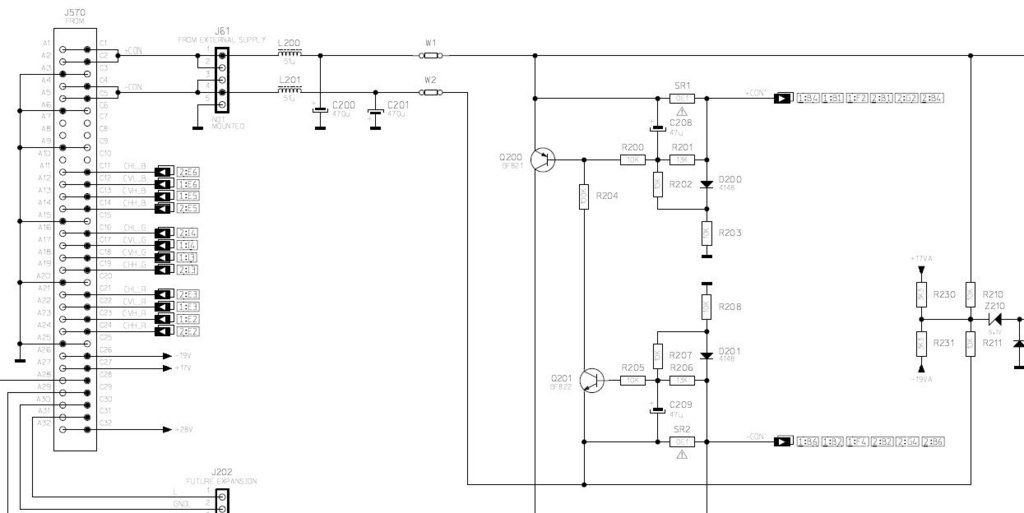
Yes I know that bulletin. On my bosrd no smd resistor is upgraded. I have to do that once. On my board an electrolytic cap close to those resistors had detached one leg. That fixed my issue but my issue was a static distorted convergence on blue. Blue somehow suffers the most on that board.
But your issue seems not related tothese resistors but more to the power.
See if Mastertech has an idea. Did you test the transistors close to the hot resistors with a diode tester? Do you know how to?
|
|
|
|
Post by Decibel on Aug 16, 2015 1:39:37 GMT -5
No I don't know how. Which transistors? Q200 and Q201?
|
|
Deleted
Deleted Member
Posts: 0
|
Post by Deleted on Aug 16, 2015 1:51:36 GMT -5
No I don't know how. Which transistors? Q200 and Q201? Yes you can check them like a diode. Look for the base in the schematic and then test the diode from base to collector. That one should not conduct. Thrn check from emitter to base. Should also not conduct but when measuring in the board you might measure an other conducting path. i will look at the schematics in a moment. Did you also do the test to disconnect the conv coil and co some convergence correction and see if the resistor runs hot? I suspect it will but I think Mastertech asked for the answer? |
|
Deleted
Deleted Member
Posts: 0
|
Post by Deleted on Aug 16, 2015 2:27:53 GMT -5
 Ok Q201 is a pnp transistor. How do you test that one. Look for the leg connected to R205 and the leg connected to SR2. When you put your multimeter in diode see if you have a voltage in one direction and almost a disconnection in the other. In the blocking direction there is a conducting path through R205 R206 so you should see a large voltage on the diode meter. If you see a very small voltage it means Q201 is conducting while it should not. I do not know exactly what you will read on the meter as I am not that much experienced at this but you cannot damage anything. This would be the first test to do. Of cause the projector should not be running!
|
|
|
|
Post by Decibel on Aug 16, 2015 2:36:00 GMT -5
Meantime that you posted I did latest test. I tried to put jumpers one by one.
The flicker start with inserted jumper of the section protect by SR2.
If put only jumper of section SR1 the flicker gone off.
|
|
|
|
Post by Decibel on Aug 16, 2015 2:36:51 GMT -5
So I must to check Q200 transistor
|
|
Deleted
Deleted Member
Posts: 0
|
Post by Deleted on Aug 16, 2015 2:38:36 GMT -5
Better test Q200 than.
That is a npn so between R200 and SR1 there should be almost no conduction in one of the both directions.
Oh you can compare with Q201 to see if they are identical as they should be and probable Q201 is not broken.
Ok another check. Now you know the base is at R200/R204 measure between the other two legs. There should be no conduction as i see it.
|
|
Deleted
Deleted Member
Posts: 0
|
Post by Deleted on Aug 16, 2015 2:50:54 GMT -5
This all is just a quick test to get an idea Q200 and Q201 should give identical vallues. If one is really off you could desolder that one and test proper. My guess it is Q201 because it will draw a lot of current through SR1 if broken.
|
|
|
|
Post by Decibel on Aug 16, 2015 4:15:08 GMT -5
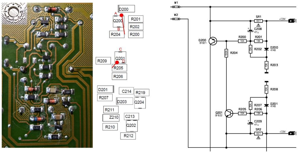
I'm not pretty able to locate the right points. Please say which are the points where I must connect the probes of meter. I indicated with red points the base of transistors, are correct?  |
|
Deleted
Deleted Member
Posts: 0
|
Post by Deleted on Aug 16, 2015 4:25:05 GMT -5
Moment. I am looking with you and they are not so easy to find.
Ok Q200 and Q201 should read OL with black left and red right. The other way 687 mV.
I am only measuring on the side with two legs.
Q200 with black on the side with 1 pin and red on any pin on the other side should read OL.
Q201 with red on the side with 1 pin and black on any pin on the other side should read OL.
These are the values I am measuring.
You have the base right.
|
|
|
|
Post by gregstv on Aug 16, 2015 5:58:21 GMT -5
The soldering on Q202 doesn't look to good at all. It could just be the picture.
|
|
Deleted
Deleted Member
Posts: 0
|
Post by Deleted on Aug 16, 2015 8:42:18 GMT -5
Looking at the schematic the most likely reason that there is a lot of current going through SR1 seems that R203 is broken. But the Q202 looks also bad and could explain it.
|
|
|
|
Post by Decibel on Aug 16, 2015 9:50:46 GMT -5
This evening I will resolder all components.
|
|
|
|
Post by mastertech on Aug 16, 2015 9:51:03 GMT -5
First off, in the attached image I have circled the solder joints that need to be repaired first. Next, when testing transistors in circuit you are really only looking for any of the 3 legs to show a low number on your meter when set to diode test. A low number would be .200 or lower. This is just for a quick test looking for a shorted transistor. After that you usually have to remove the transistor or any component that would tie any 2 legs together. After you fix those solder joints and if you do not find much with those transistors then reassemble everything and also have every thing connected and jumpers installed, post a picture of "all" your onscreen voltages again.  |
|
|
|
Post by Decibel on Aug 17, 2015 15:07:59 GMT -5
I'm thinking to buy a convergence board.
However I resolder all common smd components.
Now the resistors remain both cold.
The noise of the images remains but has changed the aspect.
I don't found a words for describe this.
I don't check the transistors because I don't understansd how to check.
|
|