|
|
Post by dolivas27 on Aug 15, 2015 3:56:38 GMT -5
Looking for some help on this one I just got in an Onkyo TX-NR636 and the power relay start to click On and Off as soon as the unit is plugged in the display never comes on.
Here is what I have checked so far I removed the power supply and tested everything on it everything seems to be fine.
I removed the relay and bench tested it with a 9v battery and it latched closed just fine of course not under any load.
Here are the voltages I am getting on connector P901B
Pin 1 M-PWR = 0 to 11.66V it's bouncing when the relay clicks.
Pin 2 +9VST = 0V
Pin 3 GND = GND
Pin 4 12VST = 11.66V
Pin 5 SW_PWR = OV I tried to press the button when the relay is clicking and I think I see a slight voltage bump but it's hard to tell as the relay is clicking On and Off
I am thinking I might have an HDMI board problem here but I am not sure.
Thanks,
Dean
|
|
|
|
Post by mastertech on Aug 15, 2015 10:41:31 GMT -5
You need to go to the main board (the one where the harness from P901A goes to) and locate Q7016. Check it very carefully with your DMM on diode scale. Also check the solder points on this transistor and solder points on P901A and B where they are soldered to their boards.
Also make sure this board has a good ground. You can do a continuity test at connector P901B, pin 3 to chassis. Reading should be as low as holding the 2 test probes together.
|
|
|
|
Post by dolivas27 on Aug 15, 2015 14:09:22 GMT -5
Hi Mastertech,
Thanks for the help I had already looked at Q7016 and I think it might be bad but I'm not a 100% sure. This transistor is not testing like other transistors I have tested is that because it has build in resistor?
Ok I just rechecked the Q7016 and I think it's good. I checked it with one that was on a TX-NR626 HDMI board I have here and they test the same.
I resoldered the Q7016 and I also tested the ground and all looks good.
I tested for continuity from the base of Q7016 to Q7009 pin 126 and it tested fine. On the chip side I see the 220 ohm resistor is good and if I test from the other side of R7030 it tested as it should.
Could I test Q7009 Pin 126 either before R7030 or after to see if it's sending a signal out and it not turning on and off? If so would I need an oscilloscope for this or could I use a DMM?
Ok I decide to jump around the relay as I thought at that point I should be able to power the unit on. But no luck the unit is completely Dead no lights at all on the receiver. So I am thinking something might be wrong with the power supply?
|
|
|
|
Post by mastertech on Aug 16, 2015 11:50:25 GMT -5
On the power supply, disconnect the harness for P901A. Plug in the receiver, take a jumper wire and jump pins 1(mpowerd) and 3(gnd)of P901A and see if you here the relay (RL9001) latch. It should latch and unlatch just by connecting and removing the jumper wire. Should be a strong latch just like when you tested it with the 9v battery.
|
|
|
|
Post by dolivas27 on Aug 16, 2015 13:24:24 GMT -5
Ok I just tried that and the relay does latch like it should?
|
|
|
|
Post by mastertech on Aug 16, 2015 14:19:56 GMT -5
Ok, that pretty much tells us that the P/S section including the relay, suppression diode and cap are fine. So the problem is coming from the main board.
You can reconnect the P/S and anything else you have disconnected or removed. Now I am not sure just how accessible these components are for testing so if you cannot get to any let me know and we can try somewhere else.
These tests the receiver must be plugged in. Hopefully you can test for voltage on that resistor, R7030 off of pin 126. DMM on DC voltage, see if the voltage is pulsing up and down. You can test right on pin 126 if R7030 is not accessible or even the base of Q7016 , just be careful not to slip. Let me know what you get.
|
|
|
|
Post by dolivas27 on Aug 17, 2015 0:30:30 GMT -5
Ok I tested the power on resistor R7030 and the voltage is pulsing of the main board it goes from 0V to 3.0V
|
|
|
|
Post by mastertech on Aug 17, 2015 12:22:14 GMT -5
Ok, next you have to see if the power supplying the main ic (Q7009) is also pulsing up and down. Pin 1 of Q7009 is fine for testing. Or Q7018, pin 5.
If you can test on Q7018 with the unit powered up I would rather there then on the main ic.
|
|
|
|
Post by dolivas27 on Aug 17, 2015 13:17:41 GMT -5
Ok I tested Pin 5 of Q7018 I had to tack a wire to it it's on the under side of the board.
Pin 5 is at a steady 3.3V no pulsing.
|
|
|
|
Post by mastertech on Aug 17, 2015 20:33:36 GMT -5
Ok, so that eliminates that. So next you need to remove Q7016 and then retest voltage on R7030 and see if it is still pulsing.
|
|
|
|
Post by dolivas27 on Aug 18, 2015 2:34:51 GMT -5
Ok I removed Q7016 and the voltage on R7030 is still pulsing.
Do you think we might have a corrupted Q7001 EEPROM?
|
|
|
|
Post by mastertech on Aug 18, 2015 10:18:59 GMT -5
Well you are not there yet. Can you post a picture of this main board so I know what I am looking at? Just an overall pic, nothing specific.
|
|
|
|
Post by dolivas27 on Aug 18, 2015 15:28:24 GMT -5
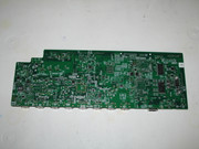
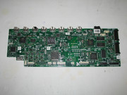
Here's the top and bottom of the main board.   |
|
|
|
Post by mastertech on Aug 18, 2015 16:21:50 GMT -5
Ok, lets try this. Leave the board out like it is and just connect the 5 wire P/S harness, plug it in and see if R7030 is still pulsing.
|
|
|
|
Post by dolivas27 on Aug 18, 2015 17:09:19 GMT -5
Ok I just tried it with the board removed and the 5 wire P/S harness connected and the voltage is sill pulsing on R7030 from 0v to 3v
|
|