|
|
Post by chriswonsowski on May 11, 2018 9:46:41 GMT -5
So I had left the receiver on for a while after I re-grounded the power supply board and came back to it a few hours later and it was off. Won't turn back on now, no indication of protection mode.
I'll try finding a faulty connection point again and also just try removing the PS board again, and leave it out for a while, then plug it back in and see what happens.
Could it be a capacitor somewhere that's bad? All the electrolytic caps look just fine.
|
|
|
|
Post by chriswonsowski on May 11, 2018 16:55:08 GMT -5
Voltage DGND to +12V is about 11.5v Voltage DGND to +10s is about 0.5v I wired in a new 12v relay because it was cheap and seems like a lot of other people had good results from it. But not this time.  |
|
|
|
Post by mastertech on May 11, 2018 17:39:10 GMT -5
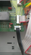
What board and what connector is that?
|
|
|
|
Post by chriswonsowski on May 11, 2018 18:20:36 GMT -5
That's coming from the PS board going to the video and speaker terminal PC board (as labelled in the service manual.
I have checked some other boards like the one that has the DTS chip and I am not getting a 12v read.
The Sirius XM board is not getting 12v.
HDMI board is not getting 12v.
AM/FM no 12v.
Unless the 12v goes to the amplifier board before going to other boards, something on the speaker terminal board has to be open.
Using chassis for ground.
This is for the HT-R557 also, not the 818, but they should be similar enough.
|
|
|
|
Post by mastertech on May 11, 2018 20:07:27 GMT -5
Ok, I have the correct manual now. This is not even close to the 818.
Get me the voltages on all 4 of those other pins using the DGND for your neg probe.
|
|
|
|
Post by chriswonsowski on May 11, 2018 20:43:12 GMT -5
I will get you those voltages. But first I'll mention this finding after taking the receiver apart: So looking at the manual, the first component after the 12v comes into the speaker terminal board is shown to be a diode D9013. My thought was going to be to follow the trace for the 12v and see at what point I find an open. Testing the diode with DMM showed 0v drop. If you look at the picture, two red circles show where the 12v line is and diode D9013 is underlined also. The two diodes circled together both gave voltage drop as they should. At this point my thought is to replace the diode.  Thinking ahead, what could have been the reason for the diode going bad? And is there a way I can bypass it to test the receiver, or is it absolutely critical that a diode is there? |
|
|
|
Post by mastertech on May 11, 2018 21:03:20 GMT -5
Hold off on replacing anything. I want to see those voltages I asked for first.
|
|
|
|
Post by chriswonsowski on May 11, 2018 21:14:39 GMT -5
You got it. I will put this back together and let you know what I get.
But is that at least correct, that something is wrong with diode D9013?
|
|
|
|
Post by chriswonsowski on May 11, 2018 22:50:46 GMT -5
Ok so I'm not getting the 12v anymore.
But anyway I sometimes get 0, .4-.6, dgnd, .4-.6, .4-.6.
Sometimes I can't get a reading though.
I noticed something else with the done before this though.
When testing it positive to anode and negative to cathode, I got 0v unlike the others which were .56 or so.
When testing it in reverse, it would start at 0v but eventually climb to .56v.
The others would stay at 0.
Then when going back to +anode/-cathode, it would start at 0v then climb up to 2v before giving me no reading on my DMM.
I had done the reverse testing on it, letting it go to .56v before reassembling everything.
Would that have any effect?
|
|
|
|
Post by mastertech on May 12, 2018 10:12:42 GMT -5
I am just interested in those voltages for now. So what did you get?
|
|
|
|
Post by chriswonsowski on May 12, 2018 11:07:57 GMT -5
Sorry I should have stated better that those were the voltages I got for that ribbon.
0v on POFF
Roughly .5v on +12V
Roughly .5v on +10s
Roughly .5v on POWERD
I used DGND for the ground.
Just for the sake of it I tested again right now.
.81 on +12V
.61 on +10S
.81 on POWERD
POFF still 0.
|
|
|
|
Post by mastertech on May 12, 2018 11:20:42 GMT -5
Ok, just to clarify, are you testing on the speaker terminal board or at the power supply board? I need you to be testing at the power supply board.
|
|
|
|
Post by chriswonsowski on May 12, 2018 11:23:20 GMT -5
Correct I have tested there at the PS board and that's what I got.
I was checking some diodes on the PS board just now in correct polarity and now the voltages at those spots are:
1.5
.75
1.5
|
|
|
|
Post by mastertech on May 12, 2018 11:27:19 GMT -5
On the PS board locate C922 and C930, set your DMM on DC voltage, plug in receiver and test across each of those caps and give me the 2 voltage readings.
|
|
|
|
Post by chriswonsowski on May 12, 2018 11:32:49 GMT -5
1.42 C922 .62 C930
|
|