|
|
Post by mastertech on Nov 4, 2015 21:41:03 GMT -5
If I remember that connector, if you push down on the top part and remove the harness, I think the top will come off if you pull out the sides a little. If you cannot get it apart to check it or if you break it, just remove the whole connector and solder the wires right into the board.
|
|
guptau
Junior Member
 
Posts: 90 
|
Post by guptau on Nov 4, 2015 22:42:13 GMT -5
By pushing down I pulled the harness a little and I could take the measurement. Pin3 has 12V on top but not in the bottom of the connector. Probably some pins are not touching the join. The connector has to be bad. I will try to push down the ribbon more and see if it works.
I another question which has been bothering me. On the power suppy, only pin3 has proper voltage, others are effectively zero. So, the expected 9V on pin2 has no purpose? Other pins also do not play any role? Thanks.
|
|
|
|
Post by mastertech on Nov 4, 2015 23:01:23 GMT -5
The 12v on the P/S is the standby voltage and it is the only voltage you will have until the main processor sends a signal back to the P/S to turn on the rest of it. You do not have this return signal so we had to look forward to see why. That 12v standby feeds 1 or more regulators that power the main CPU and the front panel button. Without that, the unit is dead.
|
|
guptau
Junior Member
 
Posts: 90 
|
Post by guptau on Nov 5, 2015 8:16:56 GMT -5
Thanks Mastertech. Can you tell me which pin gets what volage for the P/S to energize all the pins? I would like test it. Thanks.
|
|
guptau
Junior Member
 
Posts: 90 
|
Post by guptau on Nov 6, 2015 21:09:01 GMT -5
I had to solder the pins to the video board. I verified that the 3rd pin has 12.24V. I also checked that harness from video board to the HDMI board had 12V on 1st and 5th pins. I still do not see the standby light. What next? Thanks.
|
|
|
|
Post by mastertech on Nov 6, 2015 21:43:20 GMT -5
Ok, back to Q8975 , pins 1,3,5 like you tried testing before and had nothing.
|
|
guptau
Junior Member
 
Posts: 90 
|
Post by guptau on Nov 6, 2015 21:51:11 GMT -5
I will measure and let you know soon.
|
|
guptau
Junior Member
 
Posts: 90 
|
Post by guptau on Nov 6, 2015 22:13:14 GMT -5
Pin#1 = 12V, 3 = ?, 5 = 5.2V. I could not get consistent voltage on 3. |
|
|
|
Post by mastertech on Nov 7, 2015 10:54:13 GMT -5
Ok, good. It looks like you may have the pin numbers mixed up (which could be why ? on pin 3. May not of been pin 3) but the 5.2v output is what is important.
Next go to the MPU board (U0091) and find Q7013 and Q7001 and test pins 1,3,5 on each. Plugged in and DMM on DC voltage.
|
|
guptau
Junior Member
 
Posts: 90 
|
Post by guptau on Nov 7, 2015 11:57:01 GMT -5
The video board and one another board are attached to u0091 at 90 degree. I will have to disconnect these boards in order to access the ICs. It is ok to disjoin the boards, right? Thanks.
|
|
guptau
Junior Member
 
Posts: 90 
|
Post by guptau on Nov 7, 2015 12:52:42 GMT -5
The were accessible and I did not have to disconnect other boards. The voltage on both ICs were the same pin wise #1 = #3 = #5 = 1.156V. What next? Thanks.
|
|
guptau
Junior Member
 
Posts: 90 
|
Post by guptau on Nov 7, 2015 14:43:40 GMT -5
Scratch above reading - I had not connected everything. I read again after connecting everything and here are the values
Q7001
-.457 ?? -.46 4.55 -.459
Q7013
4.5 ?? 4.5 4.55 2.8
Thanks. |
|
|
|
Post by mastertech on Nov 7, 2015 16:30:51 GMT -5
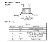
Let us concentrate on Q7001 first. Pin 1 should be 5.2v DC Pin 3 should be 3-5v DC Pin 5 should be 3.3v DC See attached for correct pin locations.  |
|
guptau
Junior Member
 
Posts: 90 
|
Post by guptau on Nov 7, 2015 16:55:58 GMT -5
I mistakenly switched the ICs in the above table. The readings did not change. For Q7001, pins 1, 2, 3 are 4.5V and pin 5 is 2.8V. I have no clue how this happening. Are the ICs faulty?
Attachments:
|
|
guptau
Junior Member
 
Posts: 90 
|
Post by guptau on Nov 7, 2015 17:49:22 GMT -5
The above was when I used chassis as gnd.
For Q7001: When I used pin# 2 of Q7013 as ground, the measurements as follows: #1 is 4.9V #3 is 5.1 and #5 is 3.2. Some how chassis is decreasing the voltages.
For Q7013: pin#1 is 4.9V and no voltage in any other pin when pin#2 of Q7001 is used as ground.
|
|