nashou
Unmoderated Off Topic
Tech in Training.....
Posts: 1,239 
|
Post by nashou on Mar 1, 2016 15:07:57 GMT -5
Well I got the amp here. Its a dirty mess. Volume post bent slightly. Looks like this will be a fun project going in blind with no schematics. Also its 100VAC. I assume I shouldn't try to plug it in but I think this may have been used that way before I got it. What do you guys with more experience say? I'll add large size photos for the experts to be able to see. And I'll add a link to this folder on my Flicker account. www.flickr.com/photos/21885221@N04/albums/72157662966343794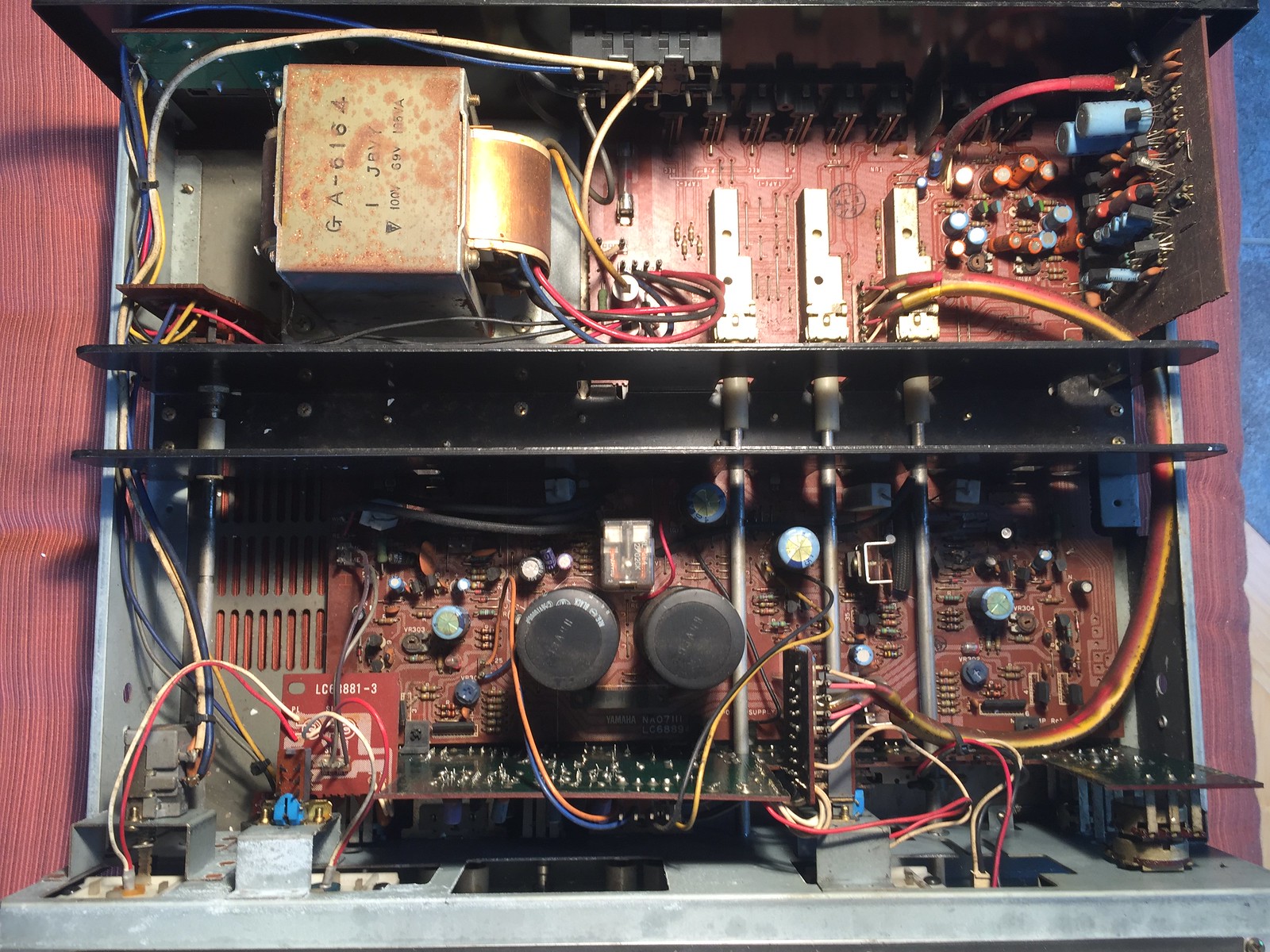 ![]() 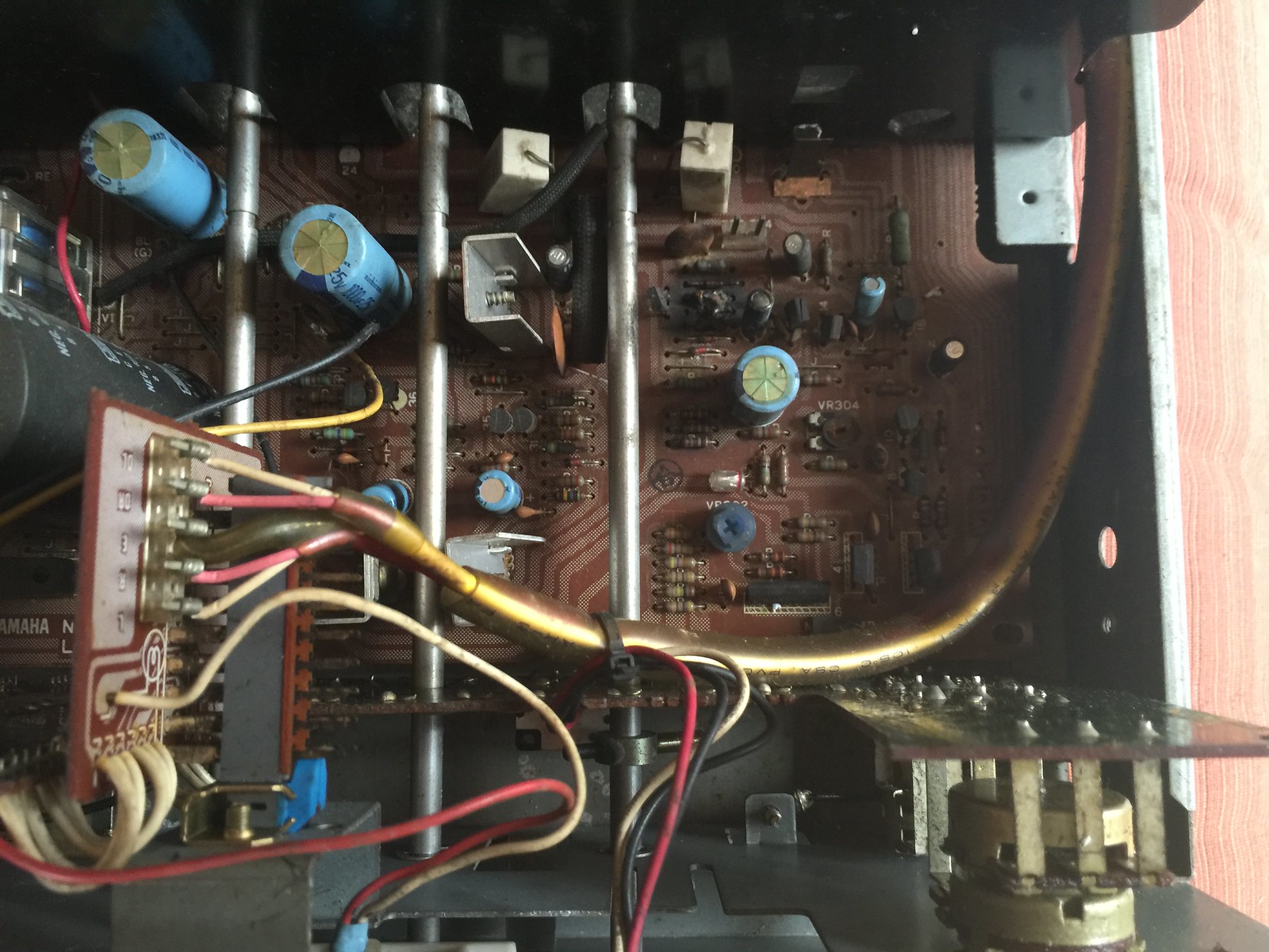 I think this might be the MC section for the phono stage. I think this might be the MC section for the phono stage.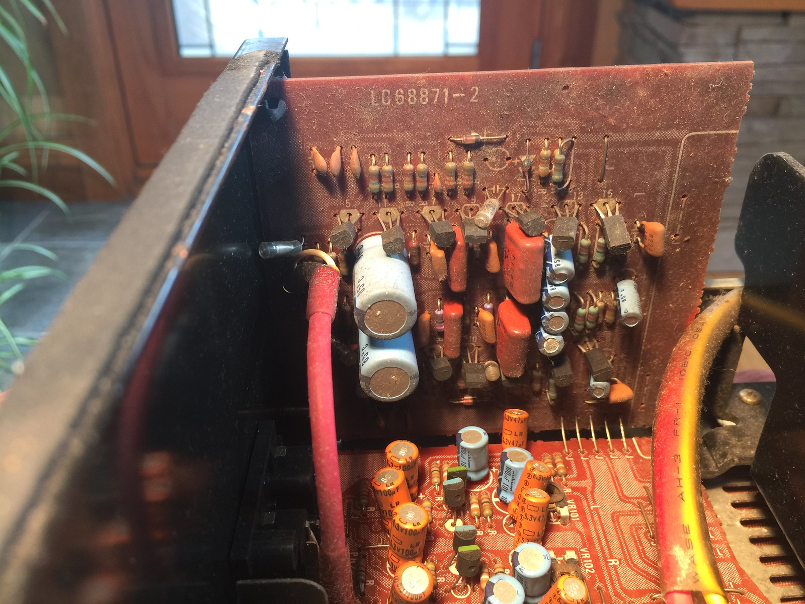 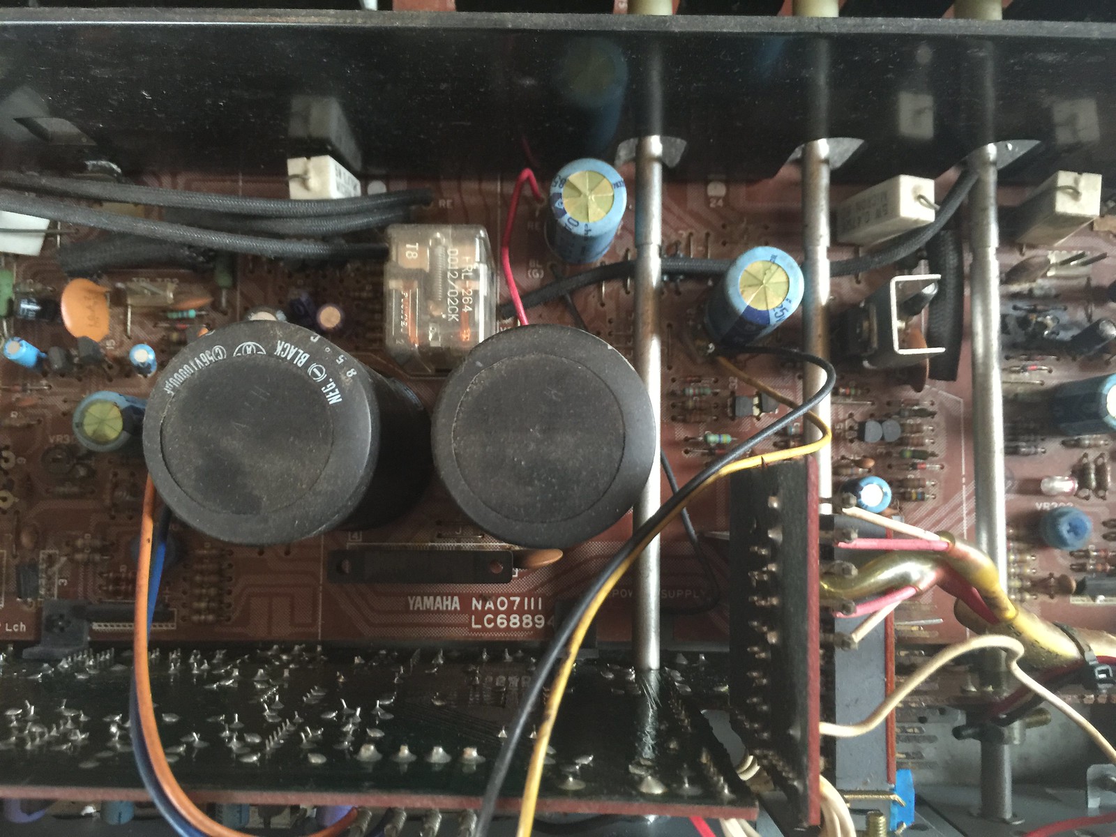 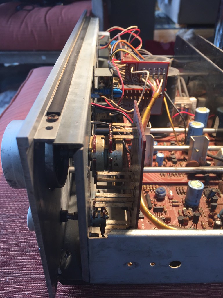 Here it looks like these caps might have a slight bulge in a couple , and you can see the burnt parts ( Just noticed this from this Picture!!! ) Here it looks like these caps might have a slight bulge in a couple , and you can see the burnt parts ( Just noticed this from this Picture!!! )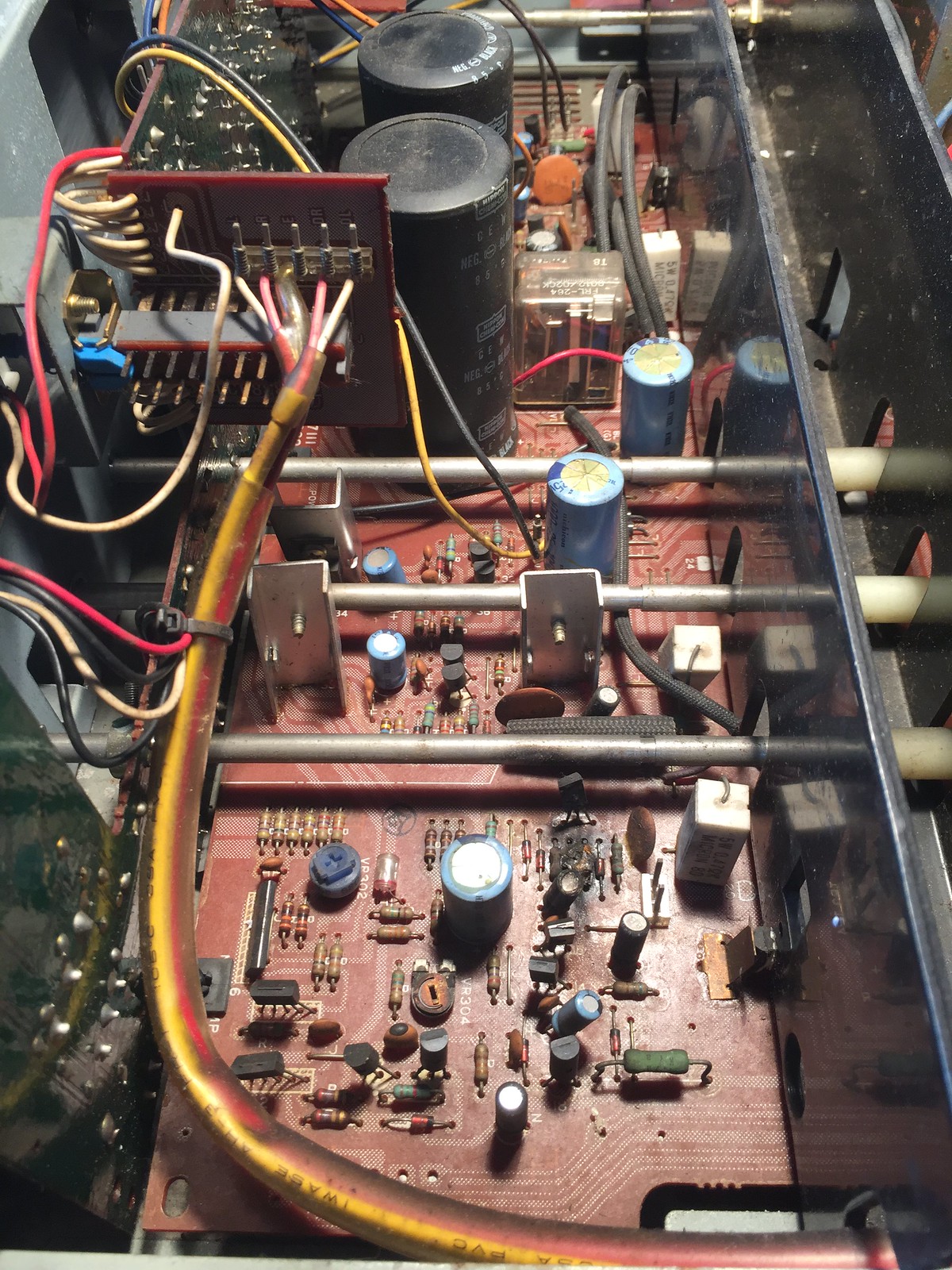 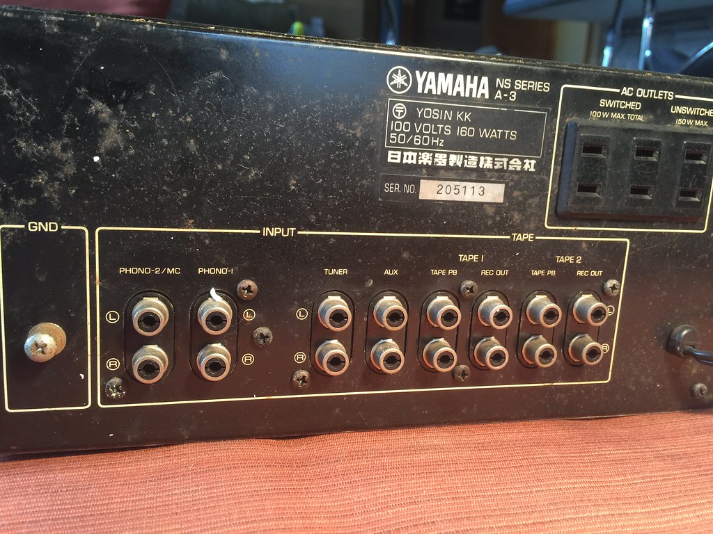 Burnt part close ups , if I can't get any info it might be a lost cause, what do you think? I'll clean up the boards and get better pics. 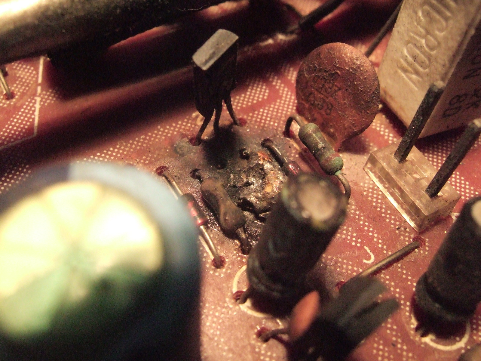 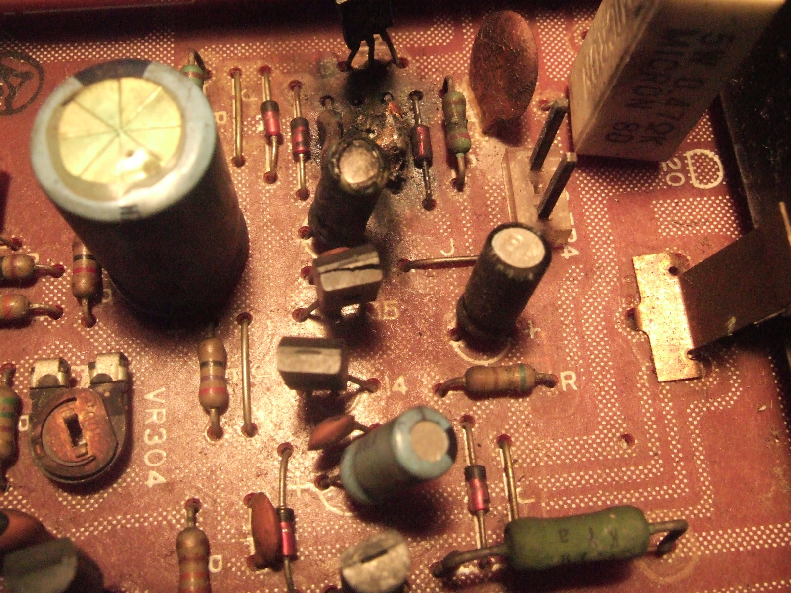 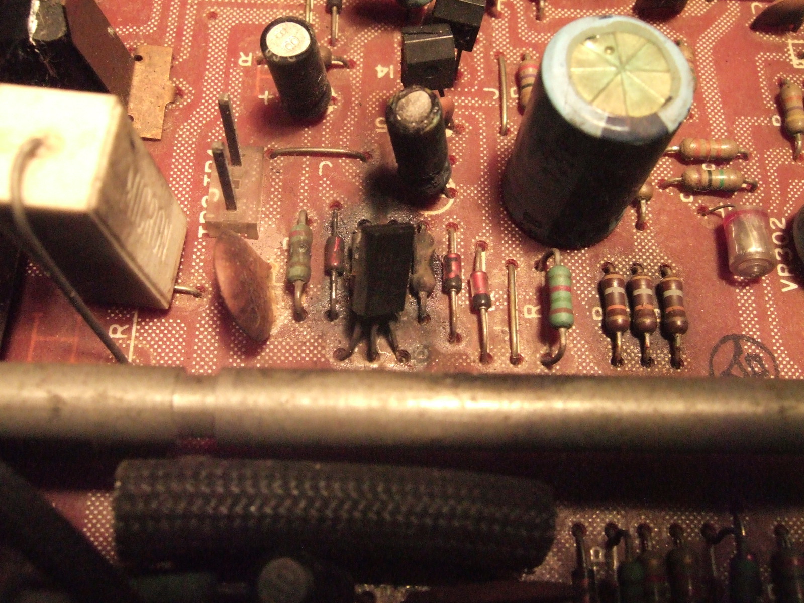 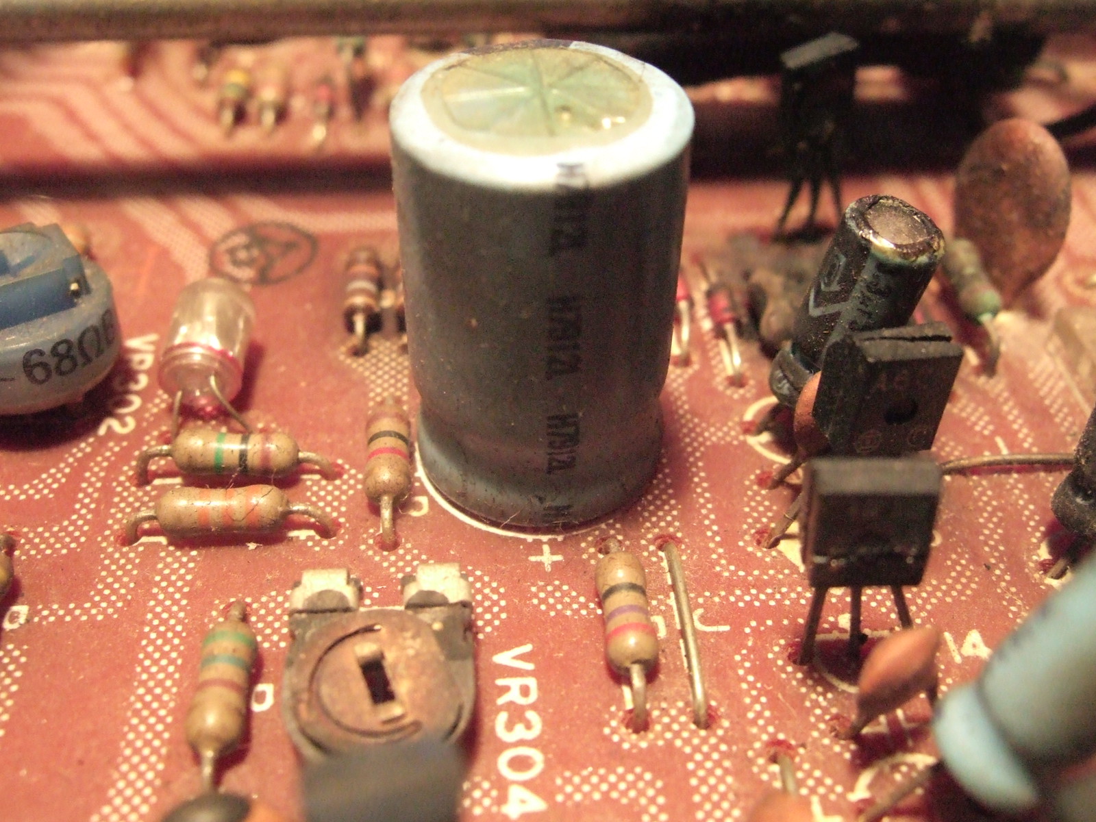 I hope you guys don't mind the big Pics . I love having them for these types of diagnostic repair threads . So if there are any Japan members here and can get me some info it be awesome!!! YAMAHA A-3 Integrated Amplifier.pdf (126.79 KB) Athanasios |
|
|
|
Post by mastertech on Mar 1, 2016 16:26:03 GMT -5
It should be no problem determining what those burnt parts are.
The 100v wording may mean the speaker line out is 100v as in a commercial system. Did you find a user manual for it?
|
|
nashou
Unmoderated Off Topic
Tech in Training.....
Posts: 1,239 
|
Post by nashou on Mar 1, 2016 17:45:54 GMT -5
It should be no problem determining what those burnt parts are. The 100v wording may mean the speaker line out is 100v as in a commercial system. Did you find a user manual for it? No User manual, no Service Manual, no schematics, no Dice  I took the bottom off, I am at work so I will take pics and post the traces. I might be able to get similar parts from the other channel. I think its part of the Amp . Nashou |
|
|
|
Post by mastertech on Mar 1, 2016 18:42:50 GMT -5
It should be no problem determining what those burnt parts are. The 100v wording may mean the speaker line out is 100v as in a commercial system. Did you find a user manual for it? No User manual, no Service Manual, no schematics, no Dice  I took the bottom off, I am at work so I will take pics and post the traces. I might be able to can easily get similar same parts from the other channel. I think its part of the Amp . Nashou Bingo! |
|
|
|
Post by mastertech on Mar 1, 2016 19:27:05 GMT -5
Well according to a document you posted elsewhere the 100v is for the AC supply, not output. Not sure how it will act if supplied 120v.
|
|
nashou
Unmoderated Off Topic
Tech in Training.....
Posts: 1,239 
|
Post by nashou on Mar 1, 2016 20:18:34 GMT -5
Well according to a document you posted elsewhere the 100v is for the AC supply, not output. Not sure how it will act if supplied 120v. Exactly my thoughts. Some say using anything that makes heat like a heater, rice cooker etc needs the transformer but VCR's CD players, DVD players dont. Id rather be safe than sorry and get a step down transformer. Amazon has them, but this ha US plugs. Not sure id the Japan plug outlets on the transformer will fit. here are pics of the Bad channel traces, and the similar good channel traces with the same mosfet. And then the parts from the top. 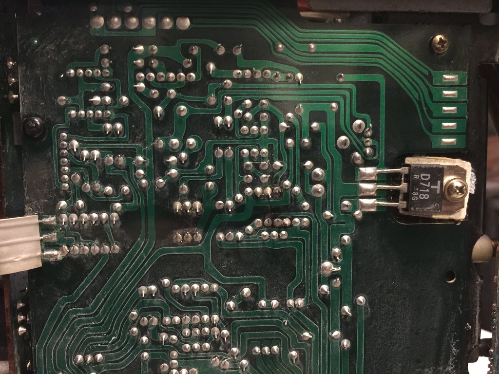 If you notice here the three wire ribbon connector has come de soldered on the good channel. Hmm, have to check all parts here too. If you notice here the three wire ribbon connector has come de soldered on the good channel. Hmm, have to check all parts here too.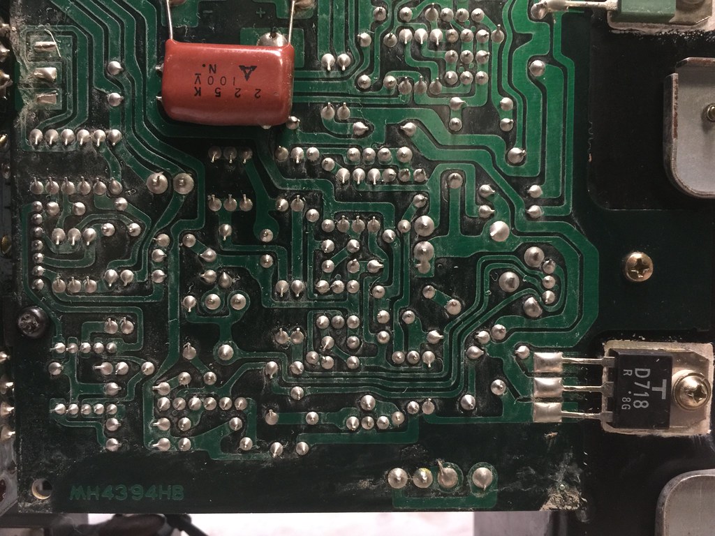 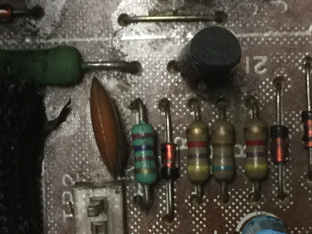 We can figure out the resistors and I bet the Diodes are the 1N4848 variant I think the ones that everyone uses for the A-1 replacements. But I'll remove them to be sure. So I'll have to remove the Transistor to read it . maybe tonight when I get home. Still waiting for the main outputs for the A-1 . Did you see the scope images? not sure what to make of it till I get the amp perts installed. |
|
nashou
Unmoderated Off Topic
Tech in Training.....
Posts: 1,239 
|
Post by nashou on Mar 1, 2016 22:59:12 GMT -5
Looks like a 2SA965 Y Ebay has them form Hong Kong in complimentary pairs. Might get those. I'll test the out put amps too just to be sure. Yep both are blown the 2SD718 and the complimentary 2SB688 I went ahead and ordered those parts and some of the other transistors in the unit. That are on the amp board. I also ordered from amazon a 1/4 watt metal 1% film resistor kit and a step down transformer to make 100v . 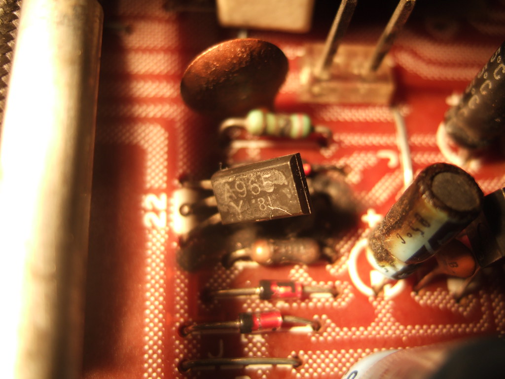 |
|
nashou
Unmoderated Off Topic
Tech in Training.....
Posts: 1,239 
|
Post by nashou on Mar 26, 2016 21:38:59 GMT -5
Well began removing parts, that board got fried !! Almost right through. Some traces will need to be repaired or just use fly wire. here are the parts removed so far and most I have ID'd 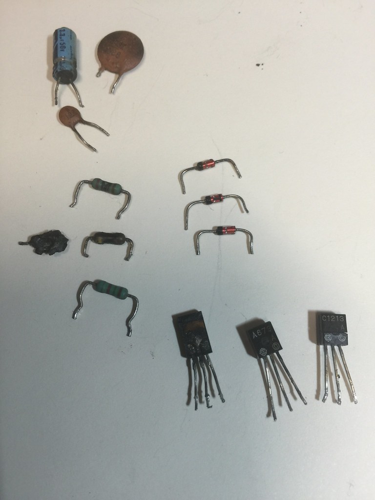 And this is the small diodes I have no idea what they are? maybe the usual in4148 for these? This just has a T ? 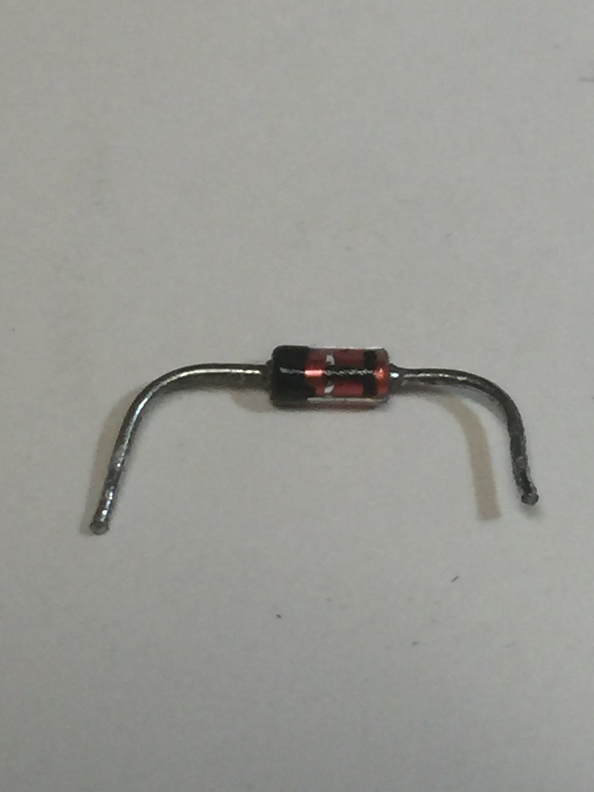 Nashou |
|
nashou
Unmoderated Off Topic
Tech in Training.....
Posts: 1,239 
|
Post by nashou on Mar 27, 2016 20:51:20 GMT -5
I guess its a 1S1555 , Yamaha used these quite a bit. I was told that the 1N4148 will work ok.
Nashou
|
|
|
|
Post by mastertech on Mar 28, 2016 12:00:19 GMT -5
Did you test those diodes to see if they are even shorted?
|
|
nashou
Unmoderated Off Topic
Tech in Training.....
Posts: 1,239 
|
Post by nashou on Mar 28, 2016 12:20:19 GMT -5
Did you test those diodes to see if they are even shorted? yep they read as resistors in my tester, about .5 ohms to 1 ohm. I did some looking at the 1S1555 specs compared to new and I found some thing close in a modern variant. This: www.mouser.com/ds/2/427/1n4154-241332.pdfOr This BA282nashou |
|
nashou
Unmoderated Off Topic
Tech in Training.....
Posts: 1,239 
|
Post by nashou on Mar 28, 2016 18:42:55 GMT -5
Took a pic of the back section of that board and drew all the parts on it from he top of board. My Head hurts!!! 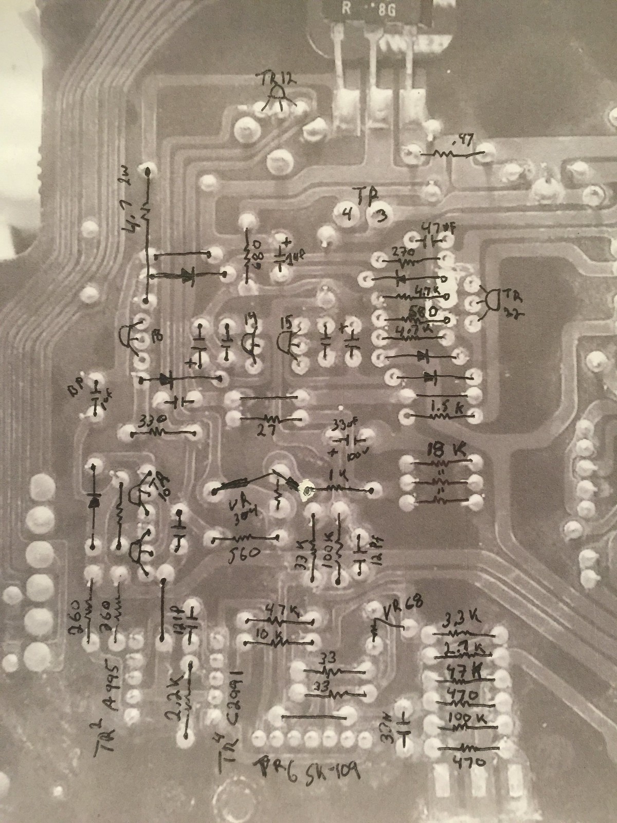 |
|
|
|
Post by mastertech on Mar 28, 2016 20:11:42 GMT -5
Well that looks like it was fun, lol.
|
|
nashou
Unmoderated Off Topic
Tech in Training.....
Posts: 1,239 
|
Post by nashou on Mar 28, 2016 20:17:51 GMT -5
Mac should I put all the parts in now, using the 1n4148's in place of the 1s1555 and leave the main output transistors out for testing?
Then I can see if the left channel works at least. I think I have to deal with a stuck speaker button on the front panel. it doesn't engage.
Athanasios
|
|
|
|
Post by mastertech on Mar 28, 2016 20:29:54 GMT -5
Well you are asking me a question that is difficult to answer. I know you looked at some schematics of a similar amp to come up with the 1s1555 but I have not seen this schematic. So I have no basis for that conclusion.
I will also add that the circuit will not run without the output transistors installed so that would not be a conclusive test. You could put anything in the diode places without the outputs it would not do a thing.
Edit: well yes, you could see if the other channel works.
|
|