|
|
Post by stridsvognen on Sept 13, 2018 20:22:21 GMT -5
The projector rurns on 2 red light and the lamp diode blinking orange. As far as i can find thats a Ballaster error, i have the ballaster out of the projector, jesus what a mess, not a very service frindly machine to work on, a miracle if i get all the plugs in again. Anyways i cant find anything on the ballaster that looks or measures defective, there is 3 NEC 2581A optoisolators, and seen a post somewhere about those going bad, how to check those, and more importantly, where to get a replacement, Digikey list them as obsolete. Any ideas what else to look for is more than welcome. 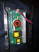 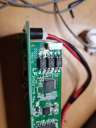
Or is it possible its just this little cap that do the trick, i have had these power up and down issues
www.fixya.com/support/t14564537-jvc_dla_x3_won_39_t_turn_off |
|
|
|
Post by mastertech on Sept 13, 2018 21:05:11 GMT -5
You did have the lamp door on when you tried the new lamp, correct?
|
|
|
|
Post by stridsvognen on Sept 13, 2018 22:38:29 GMT -5
Yes everything was in place.
I put most of the projector back together again, going to find a new cap for the IR board tomorow, and get it turned right, before i do anything else, feels a bit stupid taking it all apart, hope i did not break anything.
|
|
|
|
Post by stridsvognen on Sept 14, 2018 7:15:15 GMT -5
The IR board cap did not change much, it behave slightly differente, as the on/standby light will be gren for some time now, before it turns on red with the warning lamp, and flashing the lamp indicator orange. Im not really in a mood sending money after this projector trying a new ballaster.
|
|
|
|
Post by barclay66 on Sept 14, 2018 8:51:52 GMT -5
Hi,
the Service Manual is available on elektrotanya.com (the ZIP file one, search for DLA-X7), unfortunately no schematics for the ballast module.
It mentions that the number of blinks represents a specific fault (page 22). Maybe that helps...
Kind Regards,
barclay66
|
|
|
|
Post by mastertech on Sept 14, 2018 9:30:39 GMT -5
There are 2 things you can do to try to determine if the ballast is good or not. 1) On the ballast board there is a component called the spark gap which is usually identified by SG or SD or similar. You need to be able to see this component with everything connected and during a startup attempt. I know this can be difficult as I have done it many times. But try to find a way. Just be careful. So what to look for is when the projector is attempting to light the lamp the spark gap will have a flickering glow, usually a bluish purple. It will flicker for a few seconds and then stop for a longer period and then flicker again. It will attempt to light the lamp usually 3 times before triggering the error. If to do this test you have the lamp out of the projector on your bench and it does happen to light, turn it back off quickly since there is no fan cooling the lamp. If it does not flicker then the ballast is not trying to light the lamp. Remember there is high voltage here so be careful. 2) If the ballast is not working then you need to check the voltages to the ballast. The ballast may be fine and it is just not getting the signal to turn on or does not have the proper voltages. The 2 larger wires to the ballast from the PS should be around 390 volts IIRC. On the 5 wire harness you should have 5v supply, @5v for turn on and wattage may have a lower voltage. Another is gnd and you dont need to worry about return just yet but test it anyways to see what is there. I attached an image of the connector for reference.  |
|
|
|
Post by mastertech on Sept 14, 2018 9:38:20 GMT -5
Also remember that if you do these tests with the projector partially disassembled you need to jump the lamp door switch and any other safety devices and also all fans must be connected. Basically everything connected, just laying out on your bench if need be.
|
|
|
|
Post by stridsvognen on Sept 14, 2018 10:00:36 GMT -5
The service manual dont really point to anything specifik, but the discription in the link above is a perfect match to how mine behaves, the only thing is i dont see any issues on the ballaster, other than i can suspect those obsolete optoisolators, next step could be sourcing some replacements and change all 3 just to see what happens.
It takes a bit of will to do this, as i guess it was a 5 hour work to take it apart and put it together again. not a fun thing to work on.
Would like to have it working for the meet in Oktober, at least just to use it as a geometry reference for the CRT setup, wich is pretty much what it do best.
|
|
|
|
Post by stridsvognen on Sept 14, 2018 10:04:39 GMT -5
There are 2 things you can do to try to determine if the ballast is good or not. 1) On the ballast board there is a component called the spark gap which is usually identified by SG or SD or similar. You need to be able to see this component with everything connected and during a startup attempt. I know this can be difficult as I have done it many times. But try to find a way. Just be careful. So what to look for is when the projector is attempting to light the lamp the spark gap will have a flickering glow, usually a bluish purple. It will flicker for a few seconds and then stop for a longer period and then flicker again. It will attempt to light the lamp usually 3 times before triggering the error. If to do this test you have the lamp out of the projector on your bench and it does happen to light, turn it back off quickly since there is no fan cooling the lamp. If it does not flicker then the ballast is not trying to light the lamp. Remember there is high voltage here so be careful. 2) If the ballast is not working then you need to check the voltages to the ballast. The ballast may be fine and it is just not getting the signal to turn on or does not have the proper voltages. The 2 larger wires to the ballast from the PS should be around 390 volts IIRC. On the 5 wire harness you should have 5v supply, @5v for turn on and wattage may have a lower voltage. Another is gnd and you dont need to worry about return just yet but test it anyways to see what is there. I attached an image of the connector for reference.  Thanks ill check the main supply to the balaster asap, its a easy one, the ballaster is covered so no way i can get to it with the rest of the boards in, there is no atempt to turn on, it dont try to turn on or make any noise whatsoever |
|
|
|
Post by stridsvognen on Sept 14, 2018 10:11:49 GMT -5
Also remember that if you do these tests with the projector partially disassembled you need to jump the lamp door switch and any other safety devices and also all fans must be connected. Basically everything connected, just laying out on your bench if need be. Main problem is this thing is packed, and you need all boards out, and cables are ultra short, barely long enough to go in when everything is in place, so ill say no chance of taking it apart for testing. 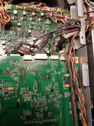 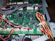 |
|
|
|
Post by stridsvognen on Sept 14, 2018 10:22:52 GMT -5
power supply seems ok, it will measure 387v for 30sec untill the lamps all turn red. I located the 5 pin and will try measure the 5v, and that conector is conected directly into the NEC optoisolators, its the white conector seen on the balaster seen on the 2nd picture in the first post, i can get to the other end of that cable as its on the top front board. 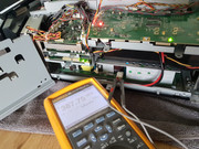 |
|
|
|
Post by stridsvognen on Sept 14, 2018 10:29:36 GMT -5
5 pin connector measure
pin 1 5v
2 GND
3 5v
4 1,5v
5 5v
|
|
|
|
Post by mastertech on Sept 14, 2018 10:58:27 GMT -5
That pin 4 (1,5v) is a problem. Can you cut the wire harness for that pin and measure the voltage on the wire part going to the sub board (not the ballast)?
|
|
|
|
Post by stridsvognen on Sept 14, 2018 11:07:55 GMT -5
That pin 4 (1,5v) is a problem. Can you cut the wire harness for that pin and measure the voltage on the wire part going to the sub board (not the ballast)? I can disconnect the plug from the board. Here is a xoom of the connector on the ballaster that i cant get to now, showing how its directly connected to the optoisolators, and wonder if its possible to measure if one of them is shorted, from what i been reading they go bad.  |
|
|
|
Post by stridsvognen on Sept 14, 2018 11:10:20 GMT -5
Ups sorry i must have had a error reading on pin 4 just tested again 5v all the line except the GND pin 2
Think it might be possible to take it all apart again, take the ballaster out, reroute the 3 cables to the ballaster, put everything else back together, and connect the balaster sitting over the HDMI board, not a fun thing, and will take at least 2 rounds of boards out before its back again, and ill admit im a bit scared that one of those flimsy connectors give up, or i damadge a board.
|
|